CARVER cORpoRRTlcIN Moral c-9 SERVICE MANUEL
SHI` 9
7.0 115/230 Lmus voL`rasE cchwERslous
Some units are equipped with AC LINE V0uTrsE conversion switches.
These are typically those which are shipped to Eurapean countries and/or
sales outlets dealing with wilitary personnel. Standard USA dnestic units
and those destined for Carmda {CSA apprchral label on rear} do not feature
such a switch and cannot be converted without exchanging the line peer
transformer. The schematic diagram shous a nonngonvertible type.
7.1 If the unit is equipped with a switch, it may be converted ty
follctwing the instructions, below. Refer to Figure 7.i for the
locations of the fuse and switch, and the sehenatic detail.
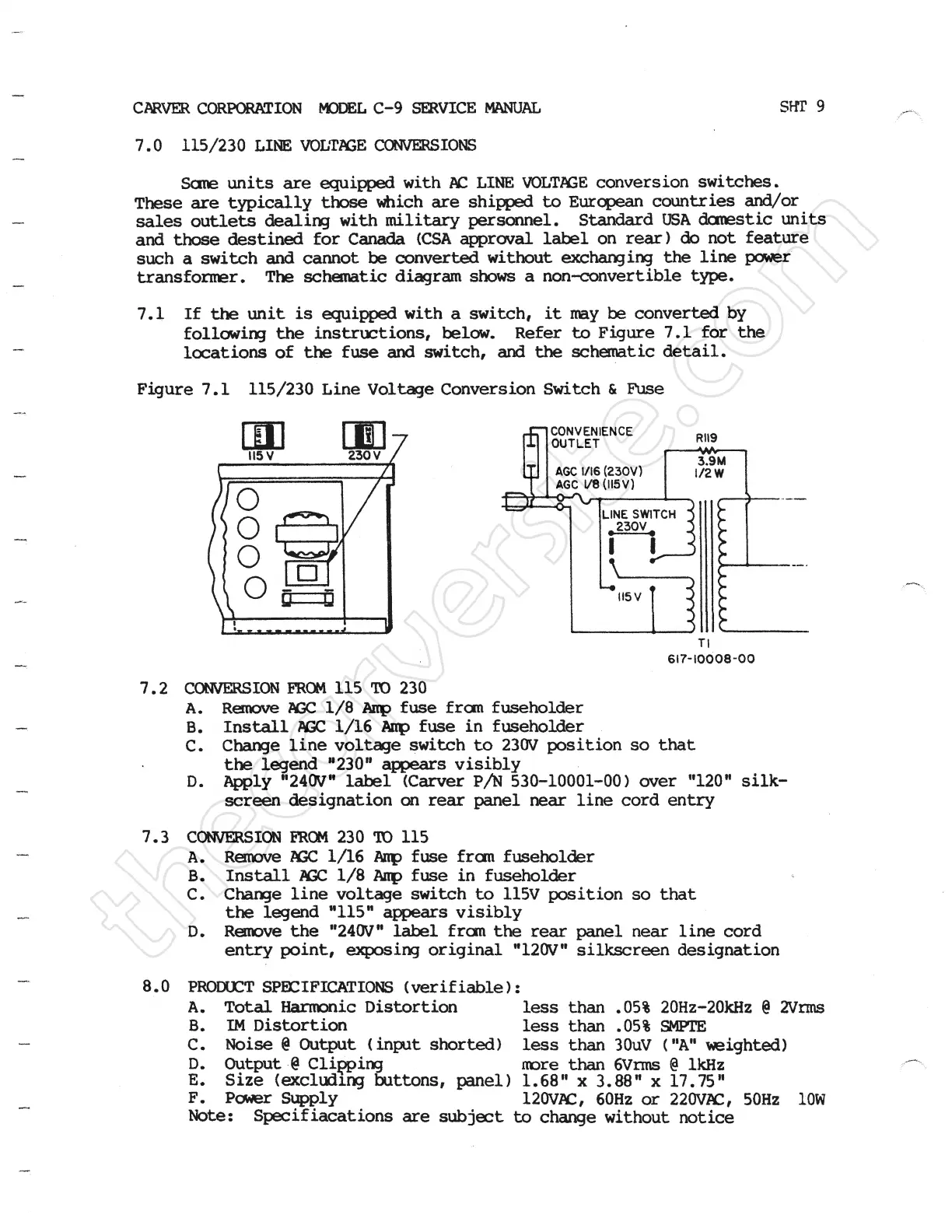
Figure 7.1 115/230 Line Voltage Conversion Switch & F\]se
Tl
61?-10008-00
7.2 cONVERsloN FROu 115 ro 23o
A. Relrove Z\GC 1/8 Axe fuse front fuseholder
8. Install AGC 1/16 Axe fuse in fuseholder
C. Change line voltage switch to 230V position so that
D. ¥i±Fgffiddr:12i¥:Prs:=e¥±£#L¥3o_iooomo ] ouer «i2o« silk-
screen designation Qn rear panel near line cord entry
7.3 cchwERslen FRou 230 ro 115
A. Renove REC 1/16 Axe fuse fran fuseholder
8. Install AGC i/8 Amp fuse in fuseholder
C. Change line voltage switch to 115V position so that
the legend "115u appears visibly
D. Renove the "24Ov" label frcm the rear panel near line cord
entry point, exposing original "120V" silkscreen designation
8.0 PRODueT SPE#IFIEAI]Ichus {verifiable } :
A. Total Harmonic Distortion less than .05% 20Hz-20kHz @ Avrms
8. " Distortion less than .05% SDRE
C. Noise a Output {inprt shorted) less than 30uV {"Att veighted}
E: #:8utfc€#Hinginttons, panel ) ¥:giltx¥.8¥F¥x ±7+#:
F. Pc]mEr Supply 120VAC, 60Hz or 220Vac, 50Hz low
Note: Speeifiacations are subject to change without notice
 Loading...