Do you have a question about the Carver CV Series and is the answer not in the manual?
Important safety warnings regarding electric shock and operational hazards.
Instructions for unpacking the amplifier and storing the original carton.
Guidance on saving sales receipts and recording serial numbers for warranty.
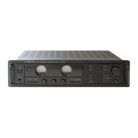
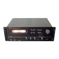
Details on power output and common features for CV1501 and CV2501 models.
Technical specs including performance, power requirements, and physical characteristics.
Details on power output and common features for CV1502 and CV2502 models.
Details on power output and common features for the CV4002 model.
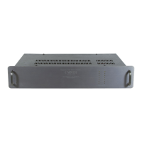
Information on removing and securing rack mounting ears for installation.
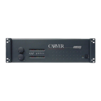
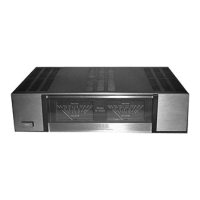
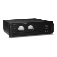
Description of level controls, VCA operation, and status/level display LEDs.
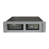
Explanation of READY, PROTECT, and THERMAL status indicator LEDs.
Details on the five LEDs per channel indicating signal level and clip status.
Explanation of how the model number designates power and channel configuration.
Details on the three-position power switch and the Standby LED indication.
Description of the Data LED, its function with the Computer Control Module.
Information on the serial number for tracking units and warranty status.
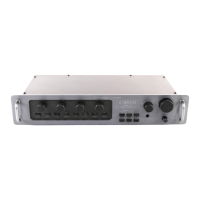
Description of the Euro Connector for speaker loads (low impedance and distributed voltage).
Details on the 3-Pin Euro Style connector for remote power sequencing ON/OFF.
Explanation of the Euro Style connector for remote level adjustment.
Description of the input module accepting balanced/unbalanced signals via XLR or Euro connectors.
Details on XLR and 3-pin Euro Style connectors for line level inputs.
Information on the IEC type AC line cord receptacle.
Guide to DIP switches for effects, clip limiter, and high pass filter settings.
Details on the 4-pin Euro Style connector for unbalanced Effects Loop send/receive.
Recommendations for amplifier placement, avoiding moisture and ensuring ventilation.
Information on rack mounting dimensions, height, depth, and securing units.
Guidance on providing mechanical support for amplifiers mounted in racks during transport.
Advice on airflow and ventilation for free-standing and rack-mounted units.
Guidance on selecting appropriate power outlets and current for amplifier operation.
Considerations for placement away from sensitive magnetic equipment.
Instructions for connecting balanced and unbalanced line level signals via XLR and Euro connectors.
Details on setting input sensitivity using jumpers for 0.775Vrms or 1.5Vrms.
Guidance on correct speaker and distributed line connection polarity for proper phasing.
Instructions for configuring and connecting the amplifier for parallel mono operation.
Instructions for configuring and connecting the amplifier for bridged mono operation.
Table detailing recommended connections for bridged mono operation with different loads.
Procedure for remotely turning a single amplifier ON/OFF using the SEQUENCE connector.
Steps for connecting multiple amplifiers for sequential power ON/OFF.
Method for verifying chassis ground continuity in rack installations.
Details on the 4-position Euro connector for remote level adjustments.
Instructions for connecting a potentiometer for remote level control.
Explanation of how VCA uses control voltage for attenuation and characteristic.
Requirements for wiring remote level controls, including wire gauge and connection notes.
Using external systems like Crestron, AMX, PANJA for level adjustment.
Recommendations for daisy-chaining the Effects Loop for signal integrity.
Details on defects in material and workmanship covered by the limited warranty.
Instructions on how to contact service and what information is required for repairs.
Information on damages not covered and state law variations.
Guidelines for cleaning the amplifier's front panel and chassis.
Contact information and procedures for obtaining technical support and service.
Checks for power supply problems, line cord, and outlet issues.
Troubleshooting steps for signal-level, cable, and speaker connection problems.
Diagnosing and resolving hum or interference problems during playback.
Causes and checks for distortion related to input controls, clipping, or impedance.