EasyManua.ls Logo

Carver PM-175 - User Manual

Carver PM-175
28 pages
Print Icon
To Next Page IconTo Next Page
Loading...
CARVERaudio.com
A Website Devoted to the Legacy of Bob Carver's Electronics
This, and all manuals found on CARVERaudio.com have been painstakingly scanned, compiled,
cataloged and archived by our dedicated forum members
, for the benefit of all Carver audio fanatics.
These manuals are NOT intended for resale. If you should find these manuals “For Sale” on any
website, please report your findings to us, so we may have them removed.
CARVERaudio.com
This manual is provided free, courtesy of CARVERaudio.com
Please report any sales of this manual to our forum @ www.CARVERaudio.com
Question and Answer IconNeed help?

Do you have a question about the Carver PM-175 and is the answer not in the manual?

Overview

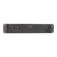
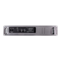
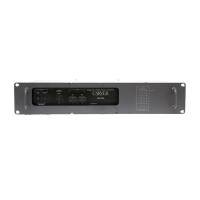
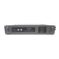
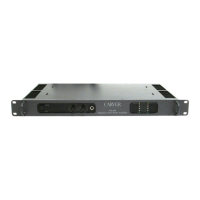
The Carver PM-175 is a professional Magnetic-Field Power Amplifier, designed to deliver high-performance audio in both touring and permanent installations. It incorporates Carver's patented Magnetic Field Power Supply technology, which contributes to its efficiency and lightweight, rugged construction. The amplifier is equipped with specially designed protection systems to safeguard both the amplifier and connected loudspeakers.

Function Description:

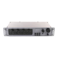
The PM-175 serves as a power amplifier, capable of operating in two primary modes: dual-channel (stereo or independent) and mono-bridged (single channel). In dual-channel mode, it can amplify a stereo pair of drive signals or two independent signals, making it suitable for bi-amplified or multi-amplified loudspeaker systems where separate low-frequency and upper-frequency elements are driven. In mono-bridged mode, the amplifier combines its two channels to deliver a single, higher-power output. The amplifier features input level controls for each channel, allowing for precise adjustment of input sensitivity and easy return to predetermined settings. It also includes visual indicators for power, signal presence, clipping, and protection status, aiding in system checkout, monitoring, and troubleshooting.

Important Technical Specifications:

  • Power Output (20-20kHz, both channels driven, ≤ 0.5% THD):
    • 8 ohms: 175 watts per channel
    • 4 ohms: 250 watts per channel
    • 2 ohms: 300 watts per channel (≤ 0.5% THD)
  • Bridging Power Output:
    • 8 ohms: 500 watts
    • 16 ohms: 400 watts
  • Total Harmonic Distortion (THD): Less than 0.5% at any power level from 20 mW to clipping.
  • Intermodulation Distortion (IMD): Less than 0.1% SMPTE.
  • Frequency Bandwidth: 5Hz-80kHz.
  • Gain: 29 dB.
  • Input Sensitivity: 1.5 Vrms.
  • Damping Factor: 200 at 1kHz.
  • Slew Rate: 25V/micro second.
  • Noise: Better than 115dB below 175 watts, A-weighted.
  • Inputs: Balanced to ground, via XLR or TRS phone jacks.
  • Input Impedance: 15k ohm each leg (total 30k ohms).
  • Input Overload Point: 7 volts RMS.
  • Compatibility: Compatible with 25 V and 70 V systems.
  • Mounting: Standard 19" rack with 3.5" space.
  • Dimensions:
    • Height: 3.5"
    • Width: 19"
    • Depth (front to back of chassis): 11.56"
  • Weight: 19 lbs.
  • AC Line Voltage Operation: Operates on AC lines from 100V to almost 140V (output power specifications are conditional to 120V/60Hz stable AC line voltage).
  • Fuse: MDX 7 or 7A, slo-blo equivalent.

Usage Features:

  • Power ON/OFF Switch: Initiates a "slow startup" to eliminate turn-on current surges.
  • Level Controls: Independent input level controls for each channel with eleven detents for precise adjustment and easy recall of settings. The left control is active during mono-bridged operation.
  • Mono-Bridging Switch: A recessed switch used to configure the amplifier for mono-bridged operation. It inverts the phase of the left channel drive signal. This switch should only be activated when the amplifier is OFF.
  • Input Connectors: Features both female XLR and TRS 1/4-inch phone jacks for balanced input signals. These connectors are wired in parallel, allowing signals to be passed on for cascading multiple amplifiers. The input impedance is 15K ohms per leg, balanced to ground, for a total of 30K ohms. The input overload point is 7 volts RMS.
  • Output Terminals (Binding Posts): Two vertical pairs of five-way binding posts that accept single- and dual-banana plugs, spade lugs, and stripped or tinned leads.
  • Grounding Scheme: A barrier strip allows for altering the grounding scheme. A factory-installed jumper connects amplifier ground to the chassis, which can be removed to help solve ground-loop hum and noise problems.
  • Accessory Module Panel: A removable panel for installing proposed signal processing modules (e.g., crossovers, compressors, noise gates) by qualified service personnel.
  • Protection Systems:
    • Slow Startup Circuitry: Prevents excessive AC line current surges during power-on.
    • Input Mute: Mutes inputs for 4 seconds during turn-on to prevent "thumps" from damaging loudspeakers if low-level driving equipment is accidentally turned on with the amplifiers.
    • Short Circuit Protection: Current limits output transistors and mutes inputs if a short-circuited load is detected. The amplifier resumes normal operation when the fault is removed.
    • Excessive High-Frequency Signal Protection: Mutes inputs if excessive high-frequency (non-musical) signals or oscillations are detected.
    • DC Offset Protection: Reduces power output if significant DC offset (2-4V DC) is present at the outputs.
    • Internal Low-Level Supply Fault Protection: Reduces power output if an internal component problem causes imbalance in the low-level power supplies.
    • Overheat Protection: Shuts down the amplifier if the heatsink temperature exceeds 90°C (194°F) and automatically switches ON when cooled to 65°C.
  • LED Indicators:
    • POWER LED (Green): Indicates the amplifier is ready for operation.
    • SIGNAL LED (Green): Indicates audio presence greater than 100 mW at either output.
    • CLIP LED (Amber): Flashes at the point of clipping for either channel, indicating headroom exhaustion.
    • PROTECT LED (Red):
      • Brightly lit: Indicates a short-circuited load or excessive high-frequency signals.
      • Dimly lit: Indicates an internal fault condition (e.g., power supply limitation, DC offset) where power supplies are limited to an extremely low output level.

Maintenance Features:

  • Cleaning: Use a soft, dry cloth for the front panel and chassis. For stubborn stains, a mild detergent on a soft cloth is recommended. Avoid ammonia, alcohol, or other strong solvents.
  • Troubleshooting Guide: The manual provides a comprehensive troubleshooting section for common issues such as LEDs off at power up, all LEDs off during operation, bright or dim Protect LED, amplifier getting wet, noise or hum, one channel dead, lack of bass, and main fuse blowing.
  • Fuse Replacement: Emphasizes replacing the fuse ONLY with the same type and rating (MDX 7 or 7A, slo-blo equivalent) to prevent amplifier damage and voiding the warranty.
  • Cable System Advice: Recommends using high-quality speaker wire (12-gauge or heavier for long runs) and proper terminations (dual-banana plugs, spade lugs, tinned leads). Advises consulting a Carver Professional Products Dealer for cable system setup.
  • Warranty: A one-year limited warranty covering defects in materials and workmanship, exclusive to the United States. It excludes damage from shipment, misuse, abuse, unauthorized modifications, or serial number alteration. The warranty extends to original or subsequent owners with a dated purchase receipt.

Carver PM-175 Specifications

General IconGeneral
BrandCarver
ModelPM-175
CategoryAmplifier
LanguageEnglish

Related product manuals