Do you have a question about the Carver PM-100 and is the answer not in the manual?
Describes the manual's sections and notational conventions used within the text.
Explains specific conventions like Note, Caution, Warning, CAPITAL, Boldface, and Italic.
Explains Carver's efficient, multiple-rail power amplifier design and its advantages.
Details the amplifier's bridging capabilities for series and parallel mono operation.
Describes the PM-100's ability to drive 70-volt distribution systems without a transformer.
Explains the feature that reduces input signal to prevent clipping and distortion.
Details protective measures for the amplifier and loads, including LED indicators.
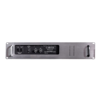
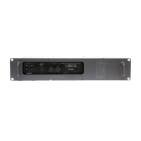
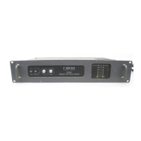
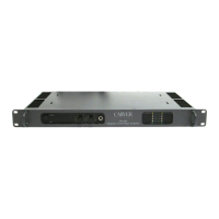
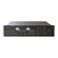
Describes controls, switches, jacks, and displays on the front panel, referencing Figure 1.
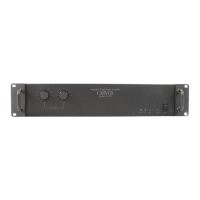
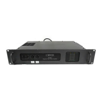
Describes rear panel features including switches, inputs, outputs, and fuse, referencing Figure 2.
Details the process for converting line voltage, requiring soldering and a technician.
Provides recommendations on amplifier placement regarding magnetic flux leakage.
Explains input/output wiring options, including screw terminals, XLR, and phone jacks.
Discusses XLR connector wiring conventions and how the PM-100 is configured.
Details how to connect loudspeakers for stereo, parallel mono, and series mono operation.
Explains the function of the ground lift strap and how to use it to break ground loops.
Details the rear panel switches for controlling operation modes like bridging.
Explains how to use the two switches for stereo, parallel mono, and series mono modes.
Describes the clipping eliminator switch and its effect on output distortion.
Provides tips and guidance for operating the PM-100 amplifier in a system.
Explains the fundamental principles behind the amplifier's design and functionality.
Details the circuitry responsible for handling low-level input signals.
Describes the main power amplification stages of the PM-100.
Explains the design and function of the amplifier's power supply.
Details the amplifier's display system and its indicators.
Explains the circuitry involved in switching between different operational modes.
Refers to the location of the amplifier's schematic diagram for technical reference.
Provides detailed procedure for converting line voltage for different regions.
Further details on XLR connector polarity configuration options.
Troubleshooting steps for when the amplifier shows no power or audio output.
Guidance for diagnosing and resolving issues with reduced or absent audio output.
Troubleshooting steps for identifying and correcting audio distortion.
Explains the meaning of illuminated protection LEDs and how to address them.
| Power Output | 100 watts per channel (8 ohms) |
|---|---|
| Frequency Response | 20 Hz to 20 kHz |
| Input Impedance | 47k ohms |
| Gain | 26dB |
| Input Sensitivity | 1V |