BI-AMP MODE:
To BI-AMP your speakers, connect your bass speaker(s) into AMP 1 and your
full-range speaker(s) into AMP 2. The front panel X-OVER switch must be in
the “OUT” position for BI-AMPING. Set the X-OVER FREQ control to 800 Hz,
as this is normally the best crossover point for most speaker systems. Now
adjust the AMP 1 and AMP 2 power amp controls to get a balance sound. For
BI-AMPING the RC210 and RL6815, be sure the bass speaker is plugged into
AMP 1 and the full-range speakers plugged into AMP 2.
FOR MAXIMUM OUTPUT:
A. To get your loudest output, use multiple speakers or enclosures. Every
time you double your speakers, your acoustic output goes up by a factor of
four. Load the amplifier down to its lowest minimum impedence for maxi-
mum RMS power
BI-AMP MODE:
B. To get high output from your RedLine bass amp from two 8 ohm speak-
ers, use the FULL-RANGE BRIDGE MODE. Set the front panel X-OVER switch
to the “IN” FULL-RANGE position. On the rear of the amp, push the BRIDGE
switch “IN”. Plug one Twist-Lok cable into the rear amp BRIDGE ONLY con-
nector and daisy-chain another Twist-Lok from speaker to speaker. Two 8 ohm
speakers will give you a total impedance of 4 ohms, which is the maximum
power from your amp. If you use two 4 ohms speakers, your amp will shut
off and go into the “protect” mode. To reset, turn your amp off and connect
only two 8 ohm speakers (or one 4 ohm) speaker to your amp when you are
in BRIDGE MODE.
10. COOLING VENTS
The rear vents are for cooling the internal power amps. Provide a minimum of 3” of clearance
for adequate ventilation. Blocking the air flow to these vents will cause the amp to thermally
protect and turn the speaker relays off. If this happens, clear the obstruction first, keep the
power on, and turn the guitar volume down allowing the amp to cool. The amp will engage
the speaker relays when cooling conditions return to normal.
11. EFFECTS LOOP
The EFF LOOP SEND and RETURN jacks are used to connect external effects into the RedLine’s
signal chain. The loop is inserted after the main EQ and compressor but before the graphic
EQ. To use the effects loop, connect the SEND jack to the input of the effects unit and connect
the RETURN jack to the output of the effects unit. The effects loop can be turned on and off
by using the optional FS22 footswitch. When the footswitch is not connected, the loop will
default to the ON position. The status of the effects loop is indicated on the front panel by a
YELLOW LED marked EFF LOOP.
12. PREAMP / DIRECT OUT XLR
The PREAMP XLR is a balanced output that can be configured in a number of different ways.
The LINE / DIR switch is used to select a pre or post pre amp feed. In the “LINE” position,
the feed is post the preamp section and contains all of the signal processing and effects that
are being used. In the “DIR” position, a direct feed is taken off of the bass guitar and is sim-
ilar to using a direct input box at the input jack. To set the output, use the DIRECT OUT LEVEL
control. A GROUND LIFT switch is also available on the preamp out XLR jack. Set this switch
for the lowest noise when using this output. When the GND / LIFT switch is depressed, the
signal ground is lifted from this jack thus eliminating any ground loops between the RedLine
preamp out and the gear it is feeding.
13 & 14. PREAMP INSERT JACKS (HI FREQ & LOW FREQ)
Both preamp inserts are TRS (Tip-Ring-Sleeve) jacks with the tip as the SEND and the ring as
the RETURN. Using a TRS (Tip-Ring-Sleeve) insert cable, the preamp signal can be sent out
via the tip to an external effects processor and then returned to the internal power amp via the
ring. Use the front amp 1 & 2 controls for level adjustments. When the X-OVER is set to full
range “in”, both outputs receive the same full range signal. When the X-OVER is set to BI-AMP
MODE “out”, AMP 1 receives the low frequency signals and AMP2 receives the high frequency
signals as set by the front panel crossover. If a standard (Tip-Sleeve) instrument cable is used,
the low and hi frequencies can be routed from the preamp to an external power amp. These
insert jacks break the signal to the internal power amplifier.
15. FOOTSWITCH
Connect the optional FS22 footswitch to remotely control the nine band graphic EQ and the
effects loop. The first button on the FS22 turns the graphic EQ on and off and the second button
turns the effects loop on and off. Any standard footswitch with a stereo plug will work.
16. PHONES JACK
A PHONES jack is provided for practicing or as a place to hook up a tuner. Use any high
quality headphones with an impedance greater than 50Ω when connecting to this jack. The
phones jack does not interrupt the amplifiers output so a tuner can be left plugged into this
jack while playing. When using a Tip / Sleeve (mono) cable to attach gear such as a tuner
to the phones jack, insert the cable to the first click mono position of the jack.
17. SPEAKER OUTPUTS
The R600/R1000 amp contains two 1/4” and two TWIST-LOK speaker output connectors,
one for each amp. The AMP 1 (LOW FREQ) jack corresponds to the AMP 1 (LOW FREQ)
and the AMP 2 (HIGH FREQ) jack corresponds to the AMP 2 (HIGH FREQ) knob on the front
panel. Multiple speakers can be attached to either the 1/4” or Twist-Lok jacks so long as the
total impedance is not below 2Ω per amp.
18. BRIDGE SPEAKER OUTPUTS
The R600 produces 600 watts (bridged mono) into a 4Ω load or 500 watts into an 8Ω load.
The R1000 produces 1000 watts (bridged mono) into a 4Ω load or 700 watts into an 8Ω
load. To activate, push the rear recessed BRIDGE switch “IN” with a pencil and plug the speak-
ers into the BRIDGE ONLY 1/4” or TWIST-LOK jacks. Pins 1+ and 1- are used on the Twist-
Lok connector. The minimum total impedance is 4 ohms.
19. INTERNAL FUSE
If there are high AC voltage surges or if the amp is used with excessive loads, the internal
fuse will protect your amp from damage. If the fuse fails, the proper replacement fuses for
120 VAC models are; R600-15 AMP and R1000-25 AMP 250VAC slow blow.
240 VAC models; R600-10 AMP and R1000-15 AMP 250 VAC slow blow.
20. AC LINE CORD
All RedLine Series bass amplifiers are supplied with detachable three conductor AC line cords.
Make sure the cord is securely inserted into the back of the unit. Never defeat the ground
of the AC line cord as it is there for your protection. If you must plug into a two prong outlet,
use a quality 3 to 2 prong grounded adapter and properly ground it.
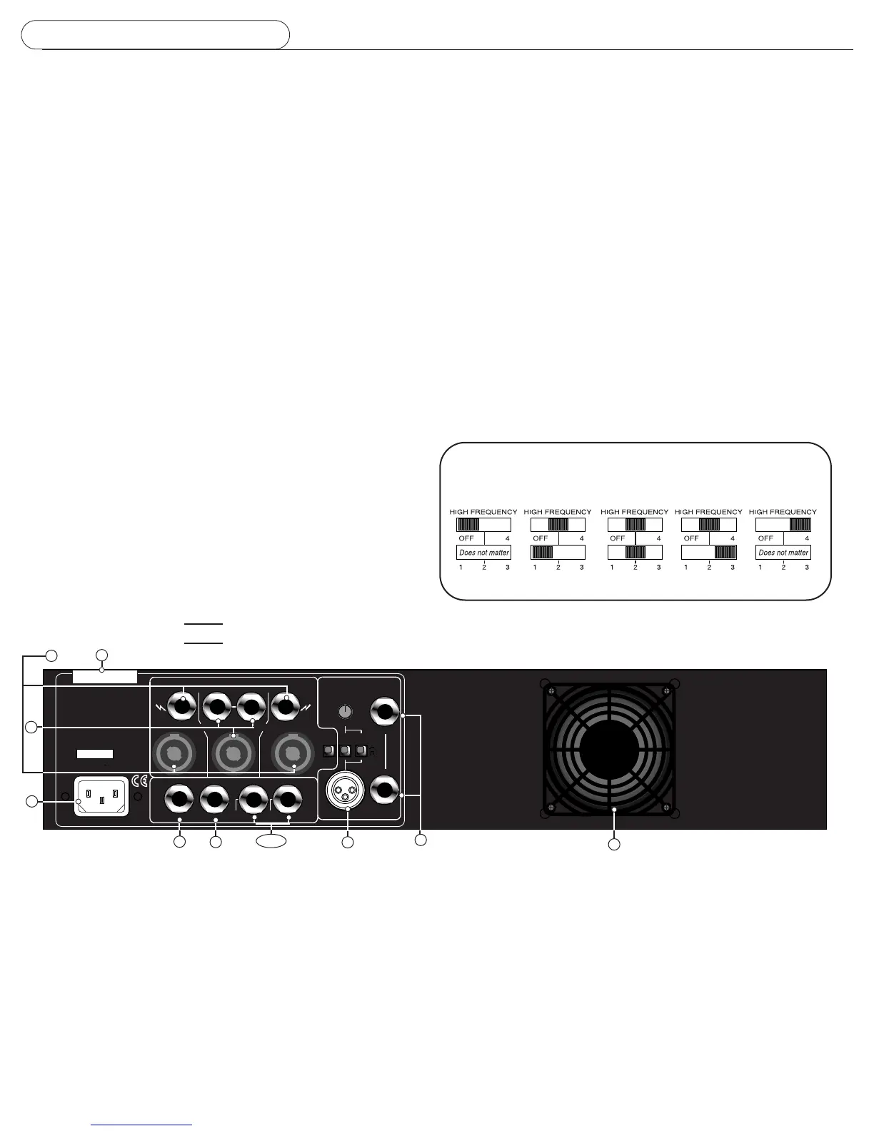
15
13 &14
20
12
11
19
INTERNAL FUSE
10
17
18
SERIES III WITH TWIST-LOK SPEAKER CONNECTORS
16
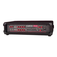
TWEETER ATTENUATOR SWITCHES (LEVELS)
For Carvin RL210T, RL410T or RL810T bass systems with tweeters.
Attenuation switches allow you to reduce your tweeter levels in 3dB increments.
REAR PANEL CONTROLS
 Loading...