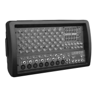
19. MONITOR OUTPUT
The MONITOR output is the same signal that feeds the inter-
nal MONITOR amp. Use this balanced output to feed
additional power amps, etc..
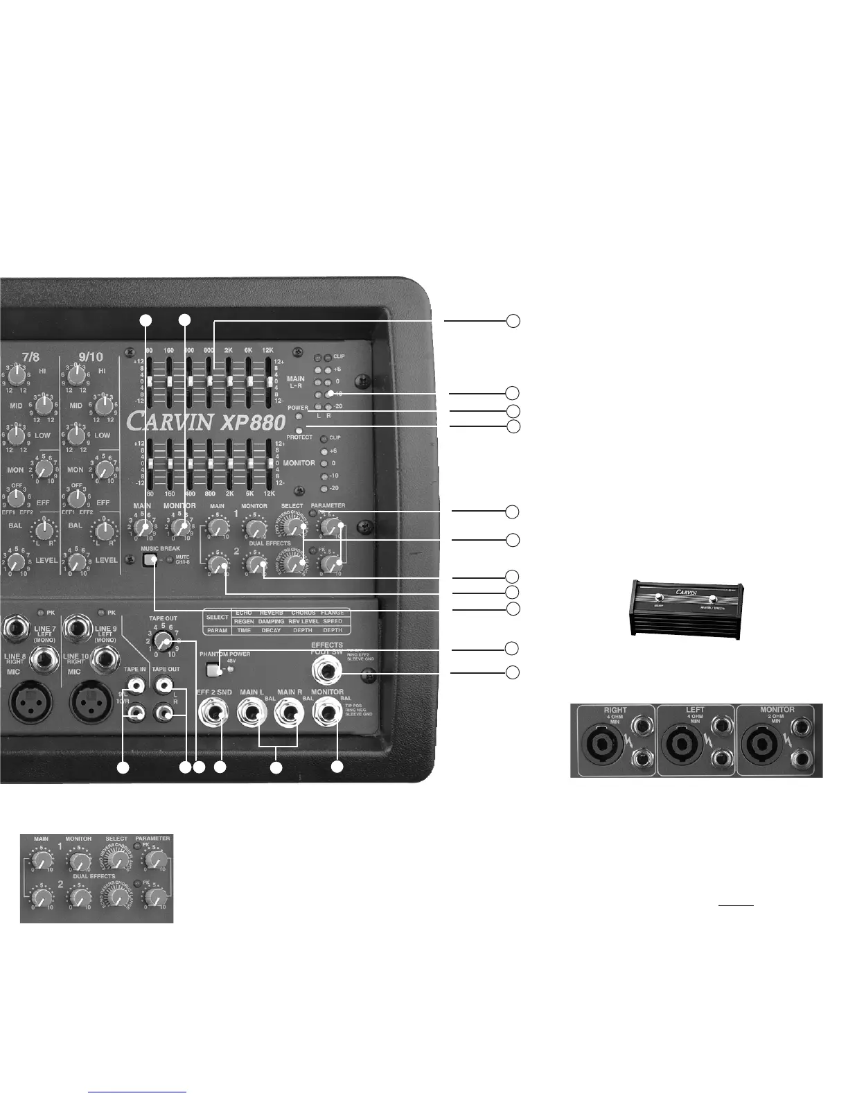
20. DUAL EFFECT PROCESSORS
Two 24-Bit processors provide a host of great sounding
effects including Flange, Reverb, Echo, & Chorus.
The channel EFF 1 & 2 send control delivers the signals to
the processors. Note: Reduce these levels if the red PEAK
LEDs are flashing at the processors.
Turn up the MAIN EFFECTS control to add your effects to the
L-R outputs. Adjust the SELECT and the PARAMETER to get
the desired effect. Note: An audible noise will be heard while
adjusting the effects.
EFFECTS cont.
A) ECHO: SELECT
the amount of the
regeneration (repeat-
ing). Now select the
PARAMETER control
for the shortest or
longest delay time
between the original
signal and the echo.
B) REVERB: SELECT the amount of presence (high frequen-
cies) in the reverb. Now turn the PARAMETER control to pro-
vide the minimum or maximum decay.
C) CHORUS: SELECT the amount of reverb with your chorus.
Now turn the PARAMETER control to increase the depth.
D) FLANGE: SELECT the amount of speed with your flange
(phasing effect). Now turn the PARAMETER control to
increase the depth.
21. EFFECTS PEAK LED’s
The PK LED indicates that the signal level to the processor is
too high. To prevent distortion, turn the EFF 1 & 2 control
towards the center (off) position until the PK LED stops flash-
ing.
22. MAIN EFFECTS CONTROL
The MAIN EFFECTS level controls the amount of the effects
that go to your L and R outputs.
23. MONITOR EFFECTS LEVEL
The MONITOR EFFECTS level controls the amount of the
effects that go to your MONITORS.
24. MUSIC BREAK SWITCH/LED
The MUSIC BREAK feature turns off all inputs, except for chan-
nel 9/10. This is useful during breaks. This allows pre-record-
ed music to be played through the TAPE IN jacks. The chan-
nel 9/10 MIC/LINE inputs are left active for announcements or
solo acts. The remaining input channels (1-8) are turned OFF
eliminating feedback or other unwanted sounds from open
mics during breaks or changes. The LED indicates the MUSIC
BREAK is ON. The internal effects are also muted.
25. GRAPHIC EQ L/R + MONITOR
When the EQ sliders are in their center position, they do not
affect the audio signal. When EQ sliders are raised or low-
ered from this position, they boost or cut a narrow fre-
quency band.
For tone enhancement you may want to raise the 80Hz and
160Hz sliders (for deeper bass) and the 6kHz and 12kHz slid-
ers (for crisper highs) while reducing the 400Hz, 800Hz and
2kHz sliders in a moderate “curve”.
To help prevent feedback, microphones should be placed
behind the main speakers.
To reduce feedback in the low frequency range, try lower-
ing one of the 80Hz or 160Hz sliders. High frequency feed-
back is usually reduced by lowering the 2kHz or 6kHz slid-
ers.
26. OUTPUT LED’s /AMP “CLIP” LED’s
The OUTPUT METER LEDs indicate the output levels for
each power amp. The yellow “+6” LED indicates the output
level is near maximum. The red CLIP LEDs indicate when
the power amps are starting to distort (clip). Reduce the
MAIN and/or MONITOR master levels to prevent distortion.
27. POWER LED
The blue POWER LED indicates the mixer is powered ON.
28. PROTECT LED
The mixer will “protect”, engaging relays to mute the speak-
ers if: a) impedance is below minimum on any amplifier b)
shorted speaker cables, or c) ventalation problems. If the
LED comes on, shut the mixer OFF and check for cable
problems, proper impedance and obstructed rear cooling
vents. If you encounter an over-heat problem, leave the
mixer ON allowing the fan to cool down the internal com-
ponents. The mixer will auto-reset in about 5 minutes.
29. 48V PHANTOM POWER
SW/LED
The 48V PHANTOM POWER switch turns on the micro-
phone phantom power in the channel XLR jacks. This
power is used for supplying a high voltage to condenser
microphones. The LED indicates the phantom power is
turned on. The phantom power will not damage conven-
tional dynamic microphones. Note: Make sure the phantom
power is switched off before connecting or disconnecting
microphones to avoid a “pop”.
30. EFFECTS FOOT SWITCH JACK
The optional FS22 will remotely shut off EFFECTS 1 or 2.
REAR PANEL-POWER/SPEAKER CONNECTIONS
The rear panel contains the POWER SWITCH and AC power
cable connection. There are 3 groups of speaker jacks. Each
group has one Speakon™ connector and two 1/4” outputs
(wired in parallel).
The L / R amps have a 4Ω MIN IMPEDANCE
(Maximum one 4Ω or two 8Ω speakers per amp).
The MONITOR amp has a 2Ω MIN IMPEDANCE
(Maximum two 4Ω or four 8Ω speakers per amp).
MAKE ALL SPEAKER CONNECTIONS BEFORE
TURNING THE
MIXER ON .
12
16
26
20
22
21
25
23
17
18
13
14
19
27
28
30
29
24
15
 Loading...