Do you have a question about the CAS Scales CL5000 Series and is the answer not in the manual?
Introduction to the CAS CL5000 series price computing printer scale.
Guidelines for installing the scale in appropriate environments to prevent damage.
Importance of being aware of personal safety during operation and maintenance.
Essential safety measures to follow when operating the scale.
Proper placement of the scale on a flat and stable surface away from drafts.
Details on the factory-set footer locations for CL5000/CL5500 and CL5500-D.
Instructions for using a shorter footer in narrow spaces.
How to properly level the scale using the adjustable legs.
Overview of the different types of CAS CL5000/CL5500 scales available.
Details on Type-I and Type-II display configurations for CL5000 and CL5500.
Details on Type-III (CL5000-G) and Type-IV (CL5500-D) displays.
Table explaining symbols and their meanings for different scale types.
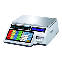
Illustration and description of the standard type keypad layout.
Illustration and description of the pole type keypad layout.
Illustration and description of the hanging type keypad layout.
Illustration and description of the self-service type keypad layout.
Illustration and description of the double body type keypad layout.
Explanation of the sealing method with diagrams.
Specifications and steps for installing the label roll.
Instructions on how to enter and navigate the PROGRAM MODE.
Detailed breakdown of the program menu structure with codes.
Tree structure for calibration related menus and functions.
Overview of weight calibration and A/D related settings.
Procedure for performing span calibration using certified weights.
Fine-tuning scale span and zero after initial calibration.
Setting weighing unit, capacity, and interval for the scale.
Setting the gravity constant for accurate calibration based on location.
Performing percent calibration when max weight is unavailable.
Re-adjusting the mid-range weight level for precise calibration.
Setting zero, tare, and overload ranges according to local regulations.
Initializes the Analog-to-Digital converter for scale settings.
Fine adjustment of linearity for improved measurement accuracy.
Performing hysteresis calibration to ensure consistent readings.
Clears all sales reports from the scale's memory.
Clears all Product Look-Up (PLU) data, including discount data.
Clears all table data except PLU and discount information.
Clears all memory, requiring reinstallation of primary data.
Setting the printer mode to label, ticket, or continuous label.
Manually inputting or measuring label and ticket dimensions.
Calibrating the printer's gap, peel, and out-of-paper sensors.
Configuring active peel-off, rewind motor, and label paper settings.
Adjusting the print intensity level for labels and tickets.
Setting the feed alignment for accurate label dispensing.
Setting the length for pre-printed labels.
Resetting the printer to its default settings.
Setting the usage of I/O interfaces like Ethernet, USB, and RS485.
Performing a test of the scale's display functionality.
Testing the Analog-to-Digital converter levels and values.
Testing the functionality of each key on the scale's keypad.
Printing a test pattern to check the thermal print head (TPH) condition.
Testing peel-off and head-up sensors in real-time.
Displaying information about the scale's memory status and capacity.
Checking the scale's firmware version for upgrades or debugging.
Adjusting the platform to prevent safety overload issues.
Step-by-step instructions for safely removing the scale's upper case.
Procedure for replacing the main circuit board of the scale.
Procedure for replacing the scale's power supply unit.
Steps for replacing the load cell and AD converter module.
Procedure for replacing the printer module assembly.
Steps for replacing the scale's display unit.
Instructions for replacing the keyboard, with and without breaking the seal.
Guide for installing an Ethernet communication card.
Guide for installing a wireless LAN card.
Guide for installing a memory expansion card in CL5000 models.
Procedure for updating the firmware of CL5000 models via RS232C.
Procedure for updating the firmware of CL5500 models via RS232C.
System block diagram for CL5000 models (B,P,R,G,S,H).
System block diagram for CL5500-D model.
System block diagram for CL5500 models (B,P,R,H,S).
Connection diagram for CL5000 models (B,P,R,G,S,H).
Connection diagram for CL5500-D model.
Connection diagram for CL5500 models (B,P,R,H,S).
Pinout details for I/O connections on CL5000 models.
Pinout details for I/O connections on CL5500 models.
Exploded view of the scale assembly for B,P,R,G types.
Exploded view of the scale assembly for H-type.
Exploded view of the body assembly for B,P,R,G types.
Exploded view of the body assembly for H-type.
Exploded view of the platform assembly for B,P,R,G types.
Exploded view of the main frame assembly for H-type.
Exploded view of the I/O cover assembly for H-type.
Exploded view of the upper case assembly.
Exploded view of the pole display assembly for R-type.
Exploded view of the pole display assembly for P-type.
Exploded view of the pole display assembly for G-type.
Exploded view of the printer assembly.
Exploded view of the printer header assembly.
Exploded view of the printer cartridge.
Exploded view of the tray assembly for B,P,R,G types.
Exploded view of the tray assembly for H-type.
Exploded view of the LAN card.
Exploded view of the self-service type scale.
Exploded view of the head cover assembly for double body type.
Exploded view of the cartridge assembly for double body type.
Exploded view of the base bracket assembly for double body type.
Exploded view of the door assembly for double body type.
Exploded view of the head assembly for double body type.
Exploded view of the tray assembly for double body type.
Exploded view of the upper assembly for double body type.
Exploded view of the platform assembly for double body type.
Exploded view of the body assembly for double body type.
List of electronic components.
List of mechanical components.
| Calibration | External Calibration |
|---|---|
| Display | LCD |
| Power Supply | AC adapter or 4 AA batteries |
| Interface | RS-232 |
| Operating Temperature | 0°C to 40°C |
| Units of Measurement | g |