B
A
F
G
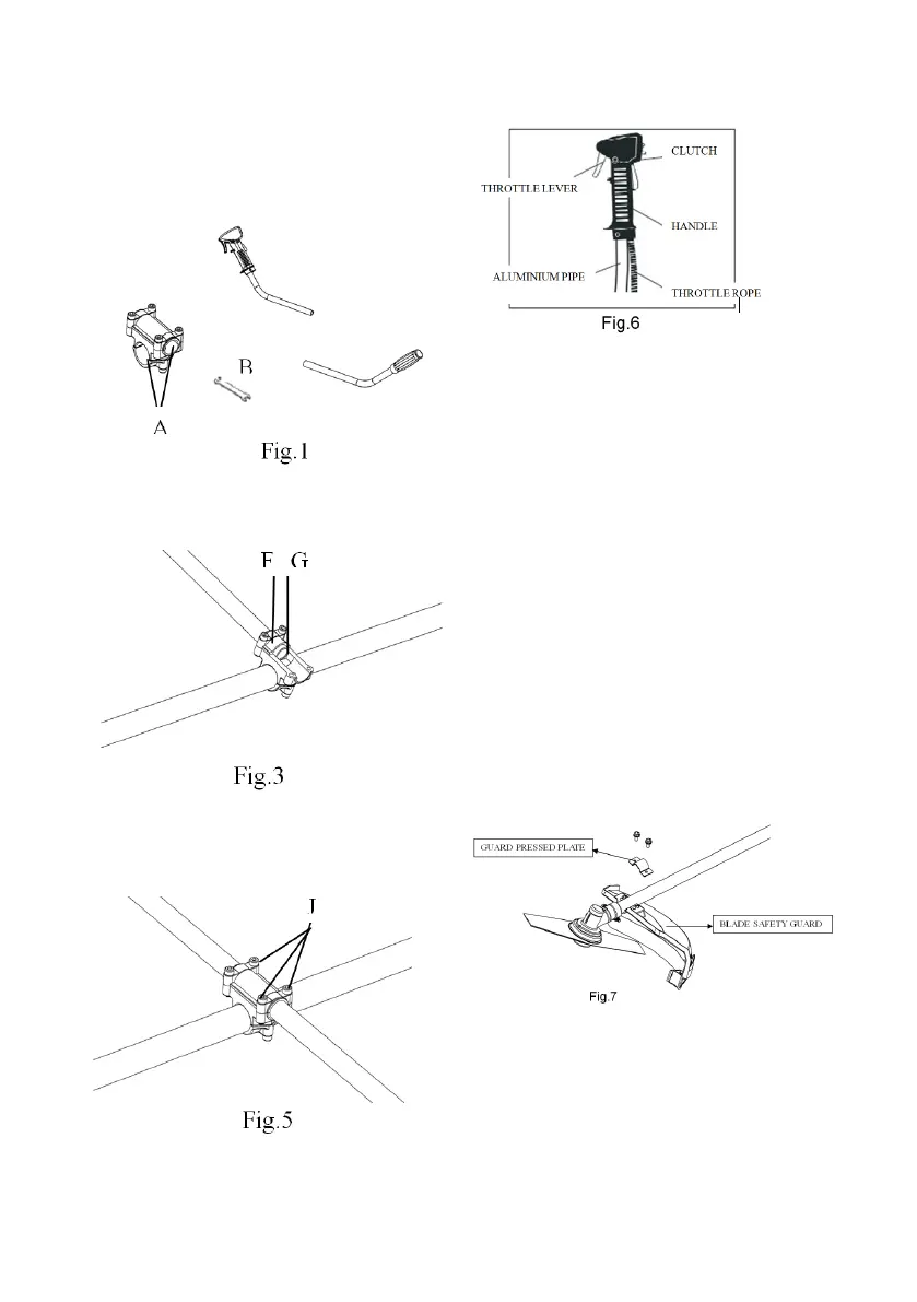
Shaft Assembly:
Handle assembly is to be installed and adjusted to a
suitable position according to your convenience and
comfort. The four bolts and nuts should be adjusted
so that the handle is secured tightly in the bracket.
(Fig.1~Fig.5)
Throttle lever and clutch diagram: (Fig.6)
Blade safety guard Installation: (Fig.7)
Slide the blade gaurd bracket onto the shaft. There
after attach the gear case assembly to the shaft. Attach
connecting metal bracket betweeen the gear case and
gaurd bracket, ensuring the holes for the screws line
up. Place the blade gaurd underneath the bracket,
alligning the holes in the blade gaurd bracket, the con-
necting bracket and the blade gaurd itself. Use the four
nuts and bolts provided to secure them all together. It
should be assembled with the nut, the tensioner, the
washer and then placed through the brackets from the
top with the bolt securing the screw from the bottom of
the blad gaurd.
There are six holes on the blade gaurd allowing the
blade gaurd to be secured in one of two positions, either
closer or further away from the shaft. Once the gaurd
and the gear case assembly are at the correct angle
on the shaft with regards to the handles, secure annd
tighten the tensioning screws.
Gear Case Part
Remove the blade fixing bolt, assemble the blade by
this sequence: cutter holder blade, cutter holder cap,
cutter fixing nut. To align the slot of gear case body
with the hole of cutter holder, insert the Allen wrench.
Then tighten the blade fixing bolt anti-clockwise with
the box wrench. (Fig.8)
 Loading...