P/N 016-0230-129 Rev. A 21
HYDRAULIC SYSTEM INSTALLATION
2. Disconnect the machine’s left and right cylinder tilt hoses from the machine’s hydraulic valve.
3. Install -6 ORFS M/M/F swivel run tee adapter fittings (P/N 333-0012-069) in the tilt hose ports of the machine’s
hydraulic block.
4. Connect the machine’s right tilt hose to the opposite end of the tee fitting installed in the right tilt port of the
machine’s hydraulic valve.
5. Connect the 90° end of the supplied hydraulic hose (P/N 214-1000-494) to the 90° end of the installed tee
fitting.
6. Connect the straight end of the installed hydraulic hose to the installed fitting in Port RC of the AutoBoom
valve.
7. Connect the machine’s left tilt hose to the opposite end of the tee fitting installed in the left tilt port of the
machine’s hydraulic valve.
8. Connect the 90° end of the supplied hydraulic hose (P/N 214-1000-494) to the 90° end of the installed tee
fitting.
9. Connect the straight end of the installed hydraulic hose to the installed fitting in Port LC of the AutoBoom
valve.
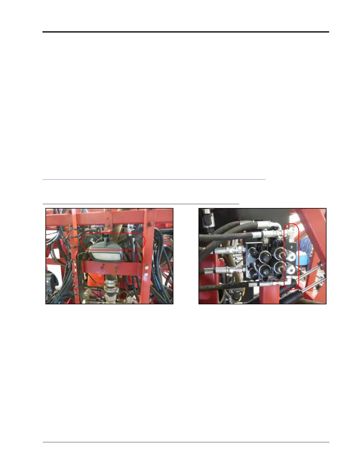
INSTALL THE LEFT AND RIGHT DOWN HOSES
FIGURE 5. Left and Right Down Hoses Installed
1. Trace the machine’s left and right cylinder return hoses from the base-end of the tilt cylinders to the machine’s
hydraulic valve.
2. Disconnect the machine’s left and right cylinder return hoses from the machine’s hydraulic valve.
3. Install -6 ORFS M/M/F swivel run tee adapter fittings (P/N 333-0012-069) in the return ports of the machine’s
hydraulic valve.
4. Connect the machine’s right cylinder return hose to the opposite end of the tee fitting installed in the right
return port.
5. Connect the 90° end of the supplied hydraulic hose (P/N 214-1000-494) to the 90° end of the installed tee
fitting.
6. Connect the straight end of the installed hydraulic hose to the installed fitting in Port RT CYL RTN of the
AutoBoom valve.
7. Connect the machine’s left cylinder return hose to the opposite end of the tee fitting installed in the left return
port.
8. Connect the 90° end of the supplied hydraulic hose (P/N 214-1000-494) to the 90° end of the installed tee
fitting.