SECTION 58 - ATTACHMENT/HEADERS - CHAPTER 4
58-2
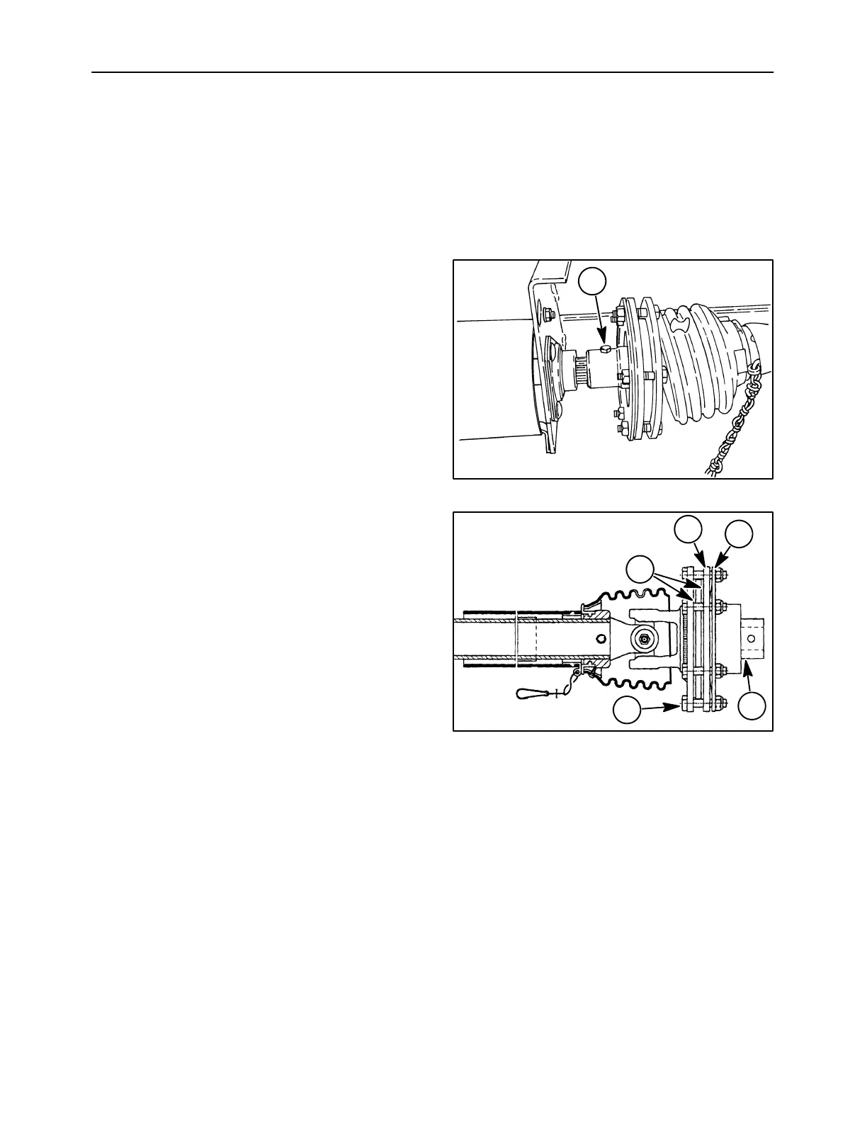
A mechanical slip clutch is used at the PTO to
prevent damage to the auger, knives or other drive
components.
The two friction discs are pressed together by a
Belleville spring. The spring tension is adjusted using
six cap screws and locknuts. If the torque required to
turn the drive components exceeds 800 N⋅ m (590 ft.
lbs.) the friction discs will allow the clutch to freely
rotate, protecting the drive components.
SLIP CLUTCH DISASSEMBLY
1. Remove the PTO shaft from the machine by
removing retaining cap screw, 1, and locknut.
Slide the shaft from the machine.
20023029
1
1
2. Remove the six cap screws and locknuts, 1.
3. Remove the Belleville spring, 2, thrust plate, 3,
and hub, 4.
4. Remove and discard the two friction discs, 5.
5. Replace any other damaged, broken, or severely
worn components with new parts.
6. Clean the friction surfaces on the flange yoke,
hub, and thrust plate with a clean cloth. Do not
get any grease or oil on the friction surfaces.
SLIP CLUTCH ASSEMBLY
1. Install a new friction disc, 5, then the hub, 4, then
the second friction disc, 5.
2. Install the thrust plate, 3, and the Belleville
spring, 2.
3. Evenly tighten the six cap screws and locknuts,
1, until the spacing between the thrust plate, 3
and Belleville spring, 2, equals 5/32″. This will
provide a clutch torque setting of 800 N⋅m (590
ft. lbs.).
4. Line up the retaining cap screw holes, and slide
the PTO shaft onto the spline jackshaft.
5. Install retaining cap screw and locknut, 1,
Figure 1.
20023027
1
2
3
4
5
2
 Loading...