SECTION 58 - ATTACHMENT/HEADERS - CHAPTER 1
58-2
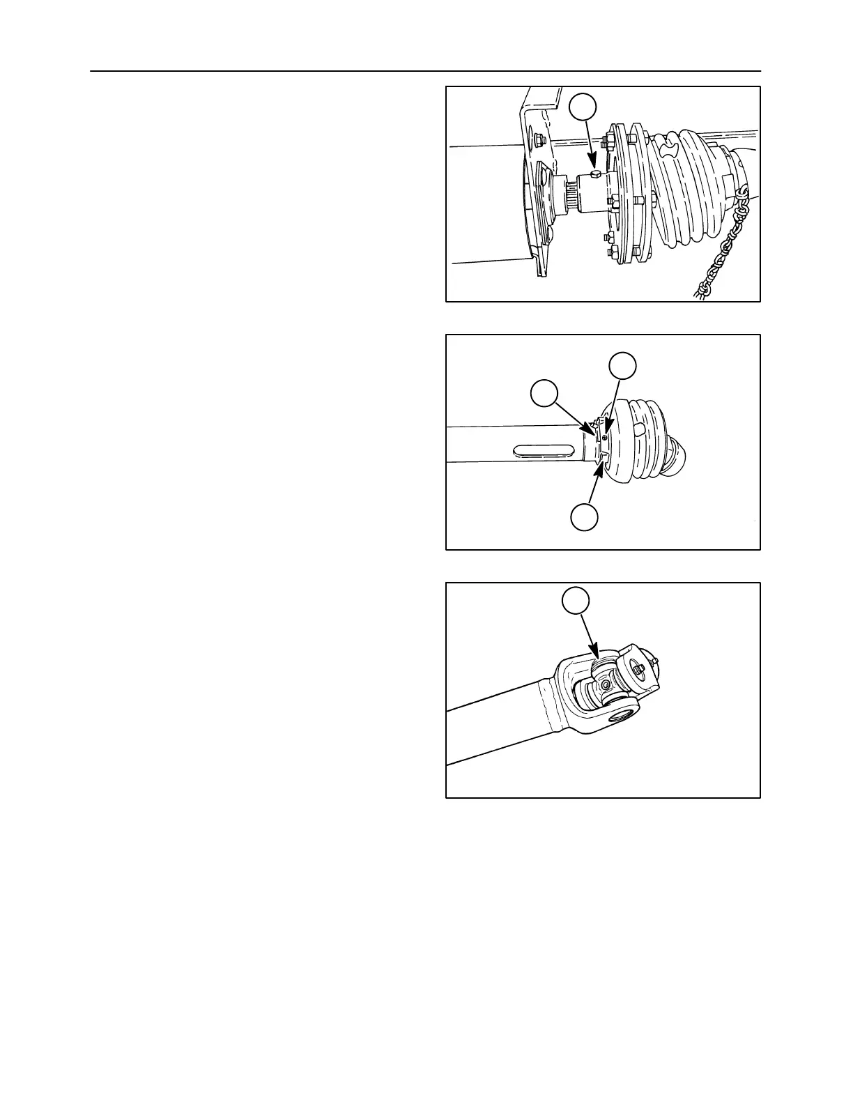
SHAFT REMOVAL
1. Remove the retaining cap screw, 1, and lock nut.
2. Slide the shaft from the machine.
20023029
1
1
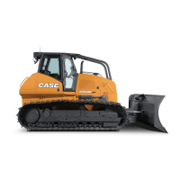
3. Separate the two shaft sections
4. Remove screw, 1, and rotate shield cone to align
slots, 2, with tabs, 3.
5. Remove the shield from the PTO.
20023032
1
2
3
2
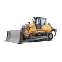
U-JOINT DISASSEMBLY
1. Remove the snap rings by positioning a
screwdriver against the open end of the snap
ring, 1, and give a light blow to the screwdriver to
pop the snap ring off the bearing cup.
1431-6-7
1
3