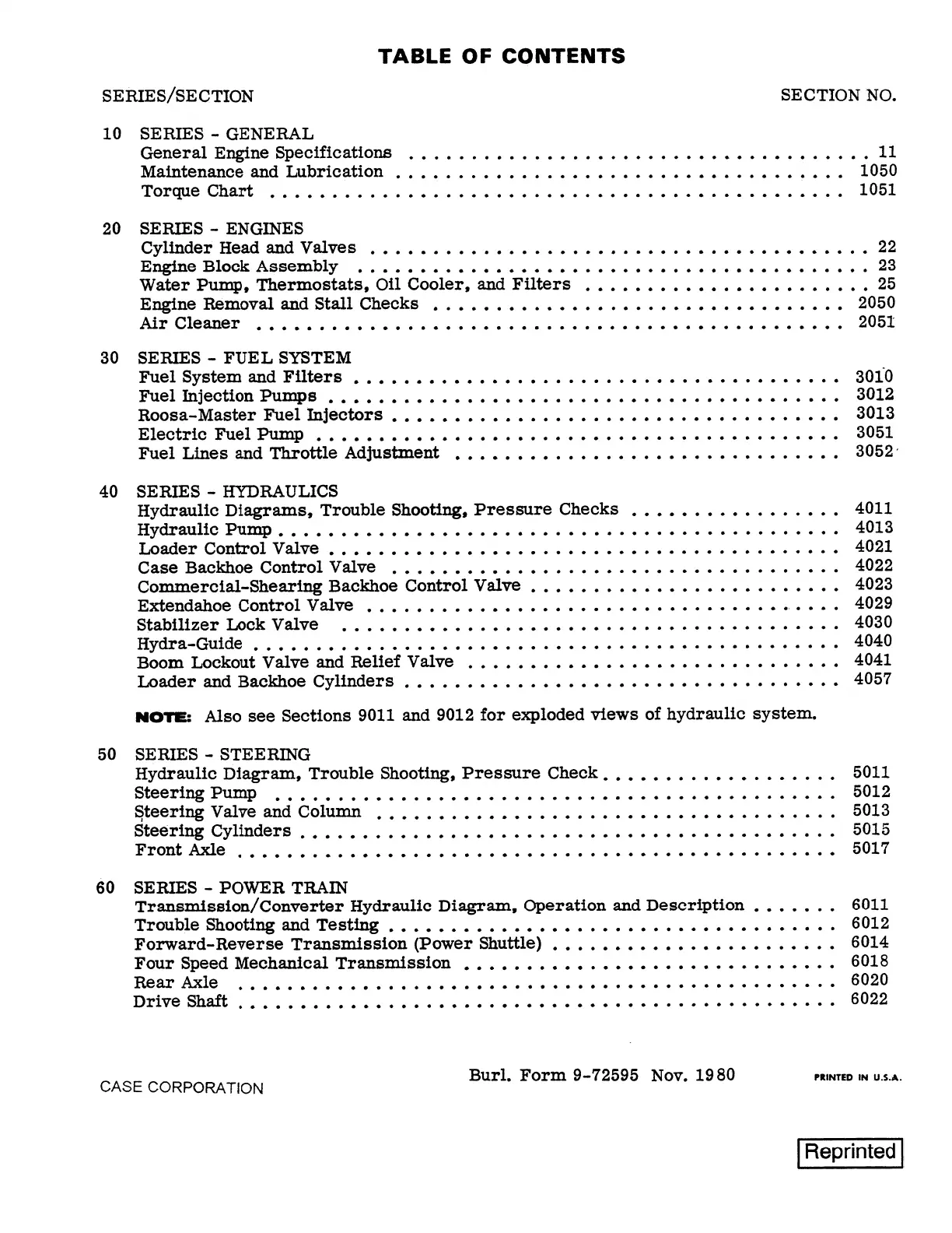
TABLE OF CONTENTS
SERIES/SECTION SECTION NO.
10
SERIES - GENERAL
General Engine Specifications • • • • • . • • • . • • • • . • • • • • • • • • • • • • • • . • • • • • .
11
Maintenance and Lubrication • • • • • • . • • • • • • • • • • . • • • • • • • • • • • • • • • • • •
1050
Torqt1e
Chart
• • • • • • • • • • • • • • • • • • • • • • • • • • • • • • • • • • • • • • • • • • • • • • 1051
20
SERIES - ENGINES
Cylinder Head
an.d
Valves
• • • • • • • • • • • • • • • • • • • • • • • • • • • • • • • • • • • • • • . • 22
Engine
Block
Assembly • • • • • • • • • • • • • • • • • • • • • • • • • • • • • • • • • • • • • • • • • 23
Water Pump, Thermostats, Oil Cooler, and Filters ••••••••••••••••••••.••
25
Engine Removal and Stall Checks • . • • • • • • • • • • • • . • • • • • • • • • • • • • • • • • •
2050
Air Clean.er
•
• • • • . • • • • • • • • • • • • • • • • • • • • • • • • • • • • • • • • • • • • • • • • • 205!
30
SERIES - FUEL
SYSTEM
Fuel System and Filters • • • • • • • • • • • • • . • • • . . • • • • . • • • • • • • . • • • • • . •
Fuel In.jection Pumps • • • • • • • • • • • • • • • • • • • • • • • • • • • • • • • • • • • • • • • • •
Roosa-Master
Fuel
Injectors •••••••••••••••.••..•••.••••••••••••
Electric
Fuel Pump • • • • • • • • • • • • • • • • • • • • • • • • • • • • • • • • • • • • • • • • • •
Fuel Lines and Throttle Adjustment ••••••••••••.••••••••••••••••••
40
SERIES - HYDRAULICS
Hydraulic Diagrams, Trouble Shooting, Pressure Checks •••••••••••••.•••
Hydraulic Pump • • • • • • • • • • • • • • • • • • • • • • • • • • • • • • • • • • • • • • • • • • • • •
I..oad.er
Control
Valve •••••••••••••••••••••••••••••••••••••••••
Case Backhoe Control Valve ••••••••••••••.•••••••••••••••••••••
Commercial-Shearing Backhoe Control Valve •••••••••••••••••••••••••
ExteDdah.oe
Control Valve ••••••••••••••••••••••••••••••••••.••••
Stabilizer I..ock
Valve
.
. . .
.
. .
.
. .
.
.
.
.
.
. . .
. . .
. .
.
. .
.
.
. .
. .
. . .
.
.
.
. .
Hydra-Guide • • • • • • • • • • • • • • • • • • . • • • • • • • • • • • • . • • • • • • • • • • • • . • .
Boom
I..ockout
Valve and Relief Valve ••••••••••••••••••••.•••••••••
I..oader
and
Backhoe Cylinders • • • • • • • • • • • • • • • • • • • • • • • • • • • • • • •••••
NOTE:
Also see Sections
9011
and
9012
for exploded views of hydraulic system.
50
SERIES - STEERING
Hydraulic Diagram, Trouble Shooting, Pressure Check ••••••••.••••••••••
Steering
Pump • • • . • . .••••••••••••••••••••••••••••••••••••••
~teering
Valve and Column •••••••••••••••••••••••••••••••••••••
Steering Cylinders • • • • • • • • • • • • • • • • • • • • • • • • • • • • • • • • • • • • • • • • • . •
Front
Axle ................................................ .
60
SERIES - POWER TRAIN
Transmission/ Converter Hydraulic Diagram, Operation and Description •••••.•
Trouble
Shooting an.d Testing
•••••••••••••••••••••••••••••••••••.
Forward-Reverse Transmission (Power Shuttle) •••••••••••••••••••••••
Four Speed Mechanical Transmission
•
•
• • • • • • • • • •••••••••••••••••••
Rear Axle
.
. .
.
.
.
.
. .
. .
.
.
. . .
. .
.
. .
. . . . .
.
. . . .
.
.
. . .
.
. .
.
. .
.
. .
.
.
.
Drive Shaft • • • • • • • • • • • • • • • • • • • • • • • • • • • • • • • • • • • • • • • • • • • • • • • •
30iO
3012
3013
3051
3052·
4011
4013
4021
4022
4023
4029
4030
4040
4041
4057
5011
5012
5013
5015
5017
6011
6012
6014
6018
6020
6022
CASE CORPORATION
Burl. Form
9-72595
Nov.
19 80
PRINTED
IN
U.S.A.
I Reprinted
I
Find manuals at https://best-manuals.com
 Loading...