22-24
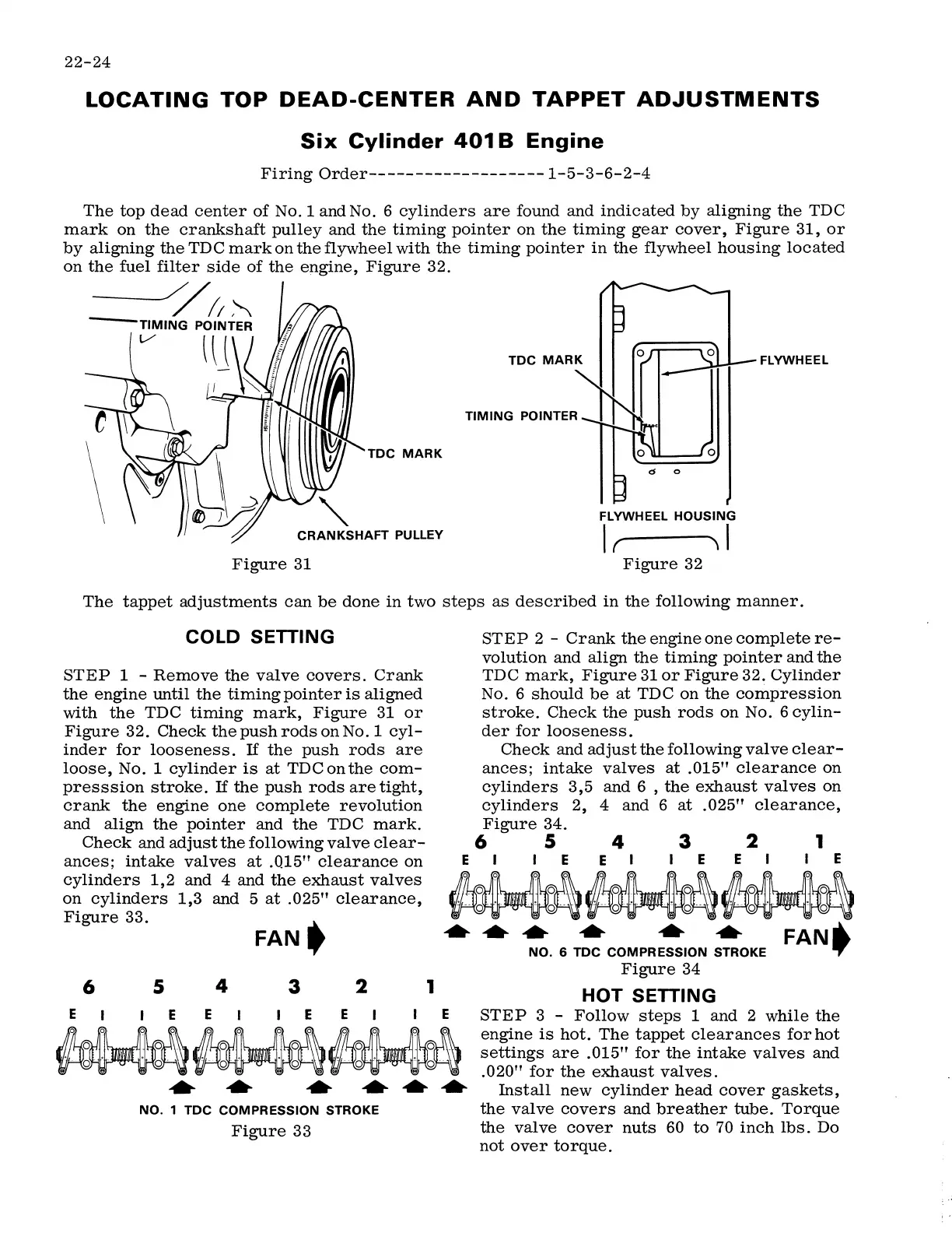
LOCATING TOP DEAD-CENTER AND TAPPET ADJUSTMENTS
Six Cylinder 401 B Engine
FiringOrder-------------------1-5-3-6-2-4
The top dead center of No. 1 and No. 6 cylinders are found and indicated by aligning the TDC
mark on the crankshaft pulley and the timing pointer on the timing gear cover, Figure 31, or
by aligning the TDC mark on the flywheel with the timing pointer in the flywheel housing located
on the fuel filter side of the engine, Figure 32.
-----//11~
TIMING POINTER
lU
FLYWHEEL
TIMING POINTER
FLYWHEEL HOUSING
CRANKSHAFT PULLEY
I ------ I
r '\
Figure 31
Figure 32
The tappet adjustments can be done in two steps as described in the following manner.
COLD SETTING
STEP 1 - Remove the valve covers. Crank
the engine until the timing pointer is aligned
with the TDC timing mark, Figure 31 or
Figure 32. Check thepushrodsonNo.1 cyl-
inder for looseness.
If the push rods are
loose, No. 1 cylinder is at TDC on the com-
presssion stroke.
If the push rods are tight,
crank the engine one complete revolution
and align the pointer and the TDC mark.
STEP 2 - Crank the engine one complete re-
volution and align the timing pointer and the
TDC mark, Figure 31 or Figure 32. Cylinder
No. 6 should be at TDC on the compression
stroke. Check the push rods on No. 6 cylin-
der for looseness.
Check and adjust the following valve clear-
ances; intake valves at .015" clearance on
cylinders 3,5 and 6 , the exhaust valves on
cylinders 2, 4 and 6 at .025" clearance,
Figure 34.
6 5 4 3 2 1
EI IEE I IEE I IE
Check and adjust the following valve clear-
ances; intake valves at .Q15" clearance on
cylinders 1,2 and 4 and the exhaust valves
on cylinders 1,3 and 5 at .025" clearance,
Figure 33.
~~~
••• • • • FAN._
NO. 6 TDC COMPRESSION STROKE .,
6
5
4
3
2
1
EI IEE I IEE I IE
~
_ooo~_ooo
0 0 0 0 _
· -· o· •. · · o · • __ o· · ·' ·o ··
Figure 34
HOT SETTING
STEP 3 - Follow steps 1 and 2 while the
engine is hot. The tappet clearances for hot
settings are .015" for the intake valves and
.020" for the exhaust valves .
.... .... .... ............
Install new cylinder head cover gaskets,
the valve covers and breather tube. Torque
the valve cover nuts 60 to 70 inch lbs. Do
not over torque.
NO. 1 TDC COMPRESSION STROKE
Figure 33
 Loading...