SERViCE MANUAL
Paragraphs 31-32
to a torque of 80-90 ft.-lbs. (110-124
N-m).
Bend corn-
ers of lock plate up against flat on cap screw heads.
Bleed air from power steering as outlined in para-
graph 21.
Modeis With Nonadjustabie (Cast)
Front Axie
31.
R&R AND OVERHAUL. Ib remove the steer-
ing cylinder, first disconnect steering hose at each
end of cylinder. Disconnect steering cylinder ball joint
end from left steering arm. Remove pivot pin at right
end of cylinder Then, lift cylinder from tractor. Drain
oil from cylinder, then thoroughly clean exterior of
cylinder.
Ib disassemble steering cylinder, clamp the flat end
of steering tube (1—Fig. 39) in a soft jawed vise so
cylinder is in vertical position. Remove small slot
head lock screw (9) and lockwasher from cylinder.
Use a filter wrench CAS-04-535 or equivalent, rotate
cylinder counterclockwise until the straight end of
retaining ring (5) can be seen through slot in cylin-
der. Pry end of retaining ring out through slot and
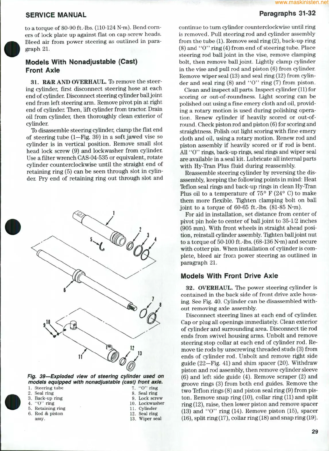
Fig. 39—Expioded view of steering cylinder used on
models equipped with nonadjustabie (cast) front axle.
1.
steering tube 7. **0" ring
2.
Seal ring 8. Seal ring
3.
Back-up ring 9. Lock screw
4.
'*0" ring 10. Lockwasher
5.
Retaining ring ' 11. Cylinder
6. Rod & piston 12. Seal ring
assy. 13. Wiper seal
continue to tum cylinder counterclockwise until ring
is removed. Pull steering rod and cylinder assembly
from the tube
(1).
Remove seal ring
(2),
back-up ring
(8) and *'O" ring (4) from end of steering tube. Place
steering rod ball joint in the vise, remove clamping
bolt, then remove ball joint. Lightly clamp cylinder
in the vise and pull rod and piston (6) from cylinder.
Remove wiper seal (13) and seal ring (12) from cylin-
der and seal ring (8) and **0" ring (7) from piston.
Clean and inspect all parts. Inspect cylinder
(11)
for
scoring or out-of-roundness. Light scoring can be
polished out using a fine emery cloth and oil, provid-
ing a rotary motion is used during polishing opera-
tion. Renew cylinder if heavily scored or
out-of-
round. Check piston rod and piston
(6)
for scoring and
straightness. Polish out light scoring with fine emery
cloth and oil, using a rotary motion. Renew rod and
piston assembly if heavily scored or if rod is bent.
All "0'* rings, back-up rings, seal rings and wiper seal
are available in a seal kit. Lubricate all internal parts
with Hy-Tran Plus fluid during reassembly.
Reassemble steering cylinder by reversing the dis-
assembly, keeping the following points in mind: Heat
Ifeflon seal rings and back-up rings in clean Hy-Tran
Plus oil to a temperature of 75° F (24° C) to make
them more flexible. Tighten clamping bolt on ball
joint to a torque of 60-65 ft.-lbs. (81-85 N-m).
For aid in installation, set distance from center of
pivot pin hole to center of ball joint to 35-1/2 inches
(905 mm). With front wheels in straight ahead posi-
tion, reinstall cylinder assembly. Tighten ball joint nut
to a torque of 50-100 ft.-lbs. (68-136 N-m) and secure
with cotter pin. When installation of cylinder is com-
plete, bleed air from power steering as outlined in
paragraph 21.
Modeis With Front Drive Axie
32.
OVERHAUL. The power steering cylinder is
contained in the back side of front drive axle hous-
ing. See Fig. 40. Cylinder can be disassembled with-
out removing axle assembly.
Disconnect steering lines at each end of cylinder.
Cap or plug all openings immediately. Clean exterior
of cylinder and surrounding area. Disconnect tie rod
ends from swivel housing arms. Unbolt and remove
steering stop collar at each end of cylinder rod. Re-
move tie rods by unscrewing threaded studs (3) from
ends of cylinder rod. Unbolt and remove right side
guide (22—Fig. 41) and shim spacer (20). Withdraw
piston and rod assembly, then remove cylinder sleeve
(6) and left side guide (4). Remove scraper (2) and
groove rings (3) from both end guides. Remove the
two Teflon rings (8) and piston seal ring (9) from pis-
ton. Remove snap ring (10), collar ring (11) and split
ring
(12),
raise, then lower piston and remove spacer
(13) and *'O'* ring (14). Remove piston (15), spacer
(16),
split ring
(17),
collar ring
(18)
and snap ring
(19).
29
 Loading...