SERVICE MANUAL
(23.37 mm) and should test 3.84
lbs.
(17
N) when com-
pressed to a length of 0.750 inch (19.05 mm). Free
length of spring (4) should be 1.525 inches (38.74 mm)
nd should test 10 lbs. (45 N) when compressed to
a length of 0.640 inch (16.26 mm). Spring
(16)
should
have a free length of 3.174 inch (80.62 mm) and
should test 30 lbs. (133 N) when compressed to a
length of 1.90 inch (48.26 mm). When reassembling,
use all new
**0**
rings and back-up rings and lubri-
cate them with petroleum jelly. Install locknut as
near to original setting as possible.
NOTE:
Position of draft vaive rod (19) tn cievis and
adjusting screw (22) in rod (19) must be adjusted af-
ter tractor is reassembied.
Lubricate draft valve parts with Hy-Tran Plus oil
during assembly. Reassemble by reversing disassem-
bly procedure.
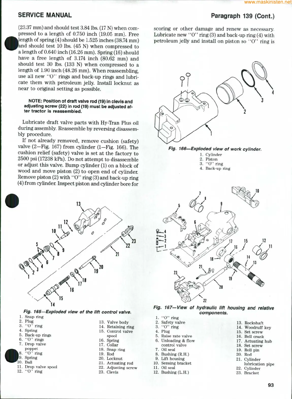
If not already removed, remove cushion (safety)
valve (2-Fig. 167) from cylinder (1-Fig. 166). The
cushion relief (safety) valve is set at the factory to
2500 psi (17238 kPa). Do not attempt to disassemble
or adjust this valve. Bump cylinder (1) on a block of
wood and move piston (2) to open end of cylinder.
Remove piston (2) with
'*0*'
ring (3) and back-up ring
(4) from cylinder. Inspect piston and cylinder bore for
Fig. 165—Exploded view of the lift control valve.
1.
Snap ring
2.
Plug 13. Valve body
3 "O'* ring 14. Retaining ring
4-
Spring 15. Control valve
5.
Back-up rings
6. **0" rings
7.
Drop valve
poppet
|8.
"O" ring
'9.
Spring
'10.
Ball
11.
Drop valve spool
12.
'*0" ring
spool
16.
Spring
17.
Collar
18.
Snap ring
19.
Rod
20.
Locknut
21.
Actuating rod
22.
Ac^justing screw
23.
Clevis
Paragraph 139 (Cont.)
scoring or other damage and renew as necessary.
Lubricate new "0'
*
ring (3) and back-up ring (4) with
petroleum jelly and install on piston so ''O*' ring is
Fig. 166—Exploded view of work cylinder.
1.
Cylinder
2.
Piston
3.
"O'* ring
4.
Back-up ring
II
22
Fig. 167—View of
1.
"O" ring
2.
Safety valve
3.
**0" ring
4.
Plug
5.
Raise rate valve
6. Unloading & flow
control valve
7.
Oil seal
8. Bushing (R.H.)
9. Lift housing
10.
Sensing bracket
11.
Oil seal
12.
Bushing (L.H.)
hydraulic lift housing and relative
components.
13.
Rockshaft
14.
Woodruff key
15.
Set screw
16.
Bellcrank
17.
Actuating hub
18.
Set screw
19.
Roll pin
20.
Rod
21.
Cylinder
lubrication pipe
22.
Cylinder
23.
Bracket
93
 Loading...