22-10
CYLINDER HEAD AND COMPONENTS (Continued)
Inspection
Replace all gaskets, seals and worn or defective parts.
1. Clean the top surface of the block and
sleeve flange carefully. All traces of
carbon and other deposits must be re-
moved. During cleaning, the use of a rag
dampened in solvent is recommended.
2. Using extreme care not to scratch sur-
faces. Remove any small burrs in the
areas to be measured so accurate read-
ings can be obtained.
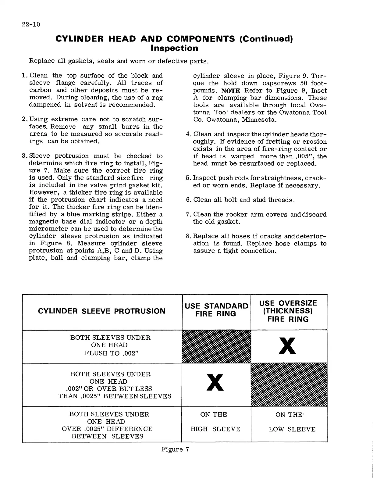
3. Sleeve protrusion must be checked to
determine which fire ring to install, Fig-
ure 7. Make sure the correct fire ring
is used. Only the standard size fire ring
is included in the valve grind gasket kit.
However, a thicker fire ring is available
if the protrusion chart indicates a need
for it. The thicker fire ring can be iden-
tified by a blue marking stripe. Either a
magnetic base dial indicator or a depth
micrometer can be used to determine the
cylinder sleeve protrusion as indicated
in Figure 8. Measure cylinder sleeve
protrusion at points A,B, C and D. Using
plate, ball and clamping bar, clamp the
CYLINDER SLEEVE PROTRUSION
BOTH SLEEVES UNDER
ONE HEAD
FLUSH TO .002"
BOTH SLEEVES UNDER
ONE HEAD
.002" OR OVER BUT LESS
THAN .0025" BETWEEN SLEEVES
BOTH SLEEVES UNDER
ONE HEAD
OVER .0025" DIFFERENCE
BETWEEN SLEEVES
cylinder sleeve in place, Figure 9. Tor-
que the hold down capscrews 50 foot-
pounds.
NOTE Refer to Figure 9, Inset
A for clamping bar dimensions. These
tools are available through local Owa-
tonna Tool dealers or the Owatonna Tool
Co. Owatonna, Minnesota.
4. Clean and inspect the cylinder heads thor-
oughly. If evidence of fretting or erosion
exists in the area of fire-ring contact or
if head is warped more than .005", the
head must be resurfaced or replaced.
5. Inspect push rods for straightness, crack-
ed or worn ends. Replace if necessary.
6. Clean all bolt and stud threads.
7. Clean the rocker arm covers and discard
the old gasket.
8. Replace all hoses if cracks and deterior-
ation is found. Replace hose clamps to
assure a tight connection.
USE STANDARD
FIRE RING
X
ON THE
filGH SLEEVE
USE OVERSIZE
(THICKNESS)
FIRE RING
X
ON THE'
LOW SLEEVE
Figure 7
 Loading...