22-12
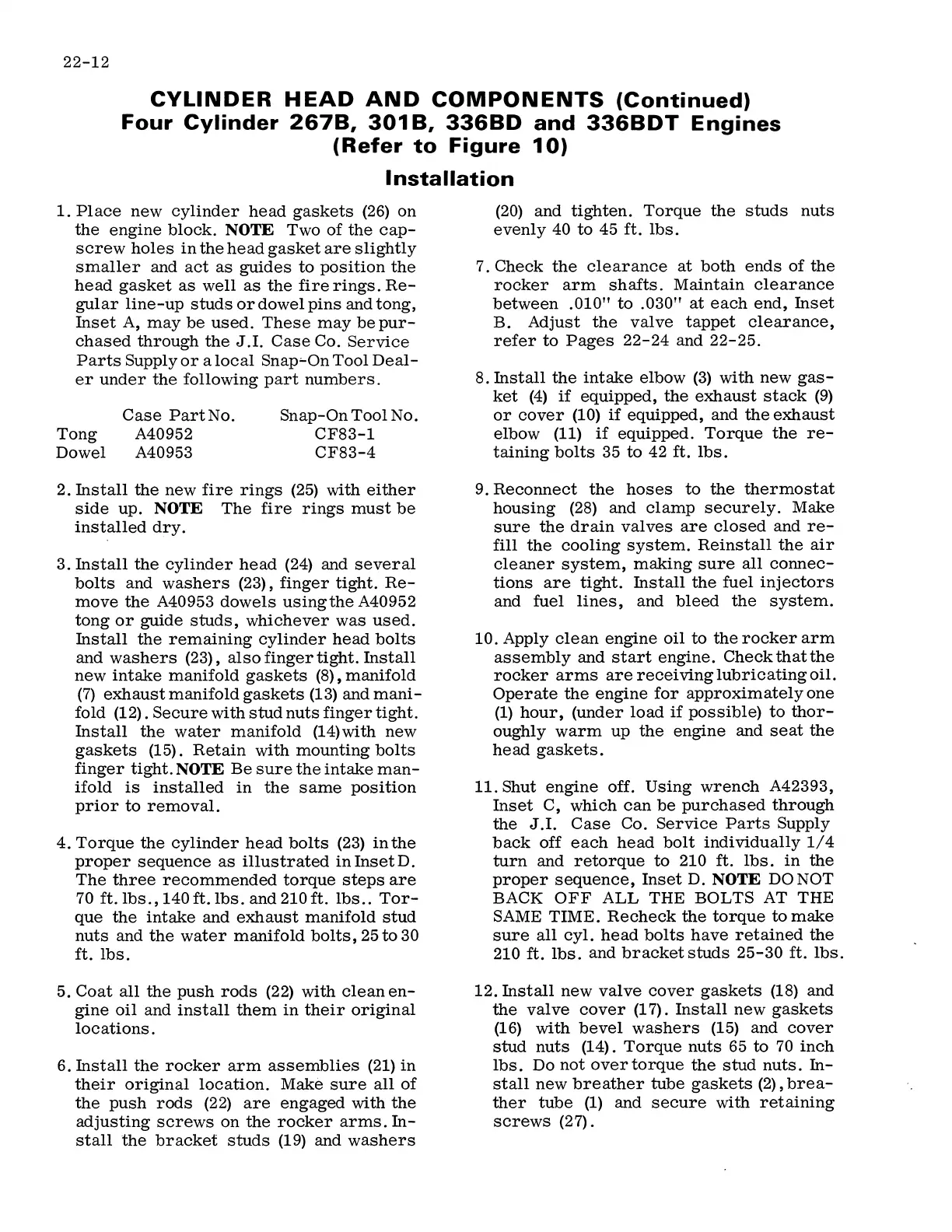
CYLINDER HEAD AND COMPONENTS (Continued)
Four Cylinder 267B, 301 B, 336BD and 336BDT Engines
(Refer to Figure 10)
Installation
1.
Place new cylinder head gaskets (26) on
the engine block.
NOTE
Two of the cap-
screw holes in the head gasket are slightly
smaller and act as guides to position the
head gasket as well as the fire rings. Re-
gular line-up studs or dowel pins and tong,
Inset A, may be used. These may be pur-
chased through the
J.I.
Case Co. Service
Parts Supply or a local Snap'-On Tool Deal-
er under the following part numbers.
Tong
Dowel
Case PartNo.
A40952
A40953
Snap-On Tool No.
CF83-1
CF83-4
2. Install the new fire rings (25) with either
side up.
NOTE
The fire rings must be
installed dry.
3. Install the cylinder head (24) and several
bolts and washers (23), finger tight. Re-
move the A40953 dowels using the A40952
tong or guide studs, whichever was used.
Install the remaining cylinder head bolts
and washers (23), also finger tight. Install
new intake manifold gaskets (8) , manifold
(7) exhaust manifold gaskets (13) and mani-
fold (12). Secure with stud nuts finger tight.
Install the water manifold (14)with new
gaskets (15). Retain with mounting bolts
finger tight.
NOTE
Be sure the intake man-
ifold is installed in the same position
prior to removal.
4. Torque the cylinder head bolts (23) in the
proper sequence as illustrated in Inset D.
The three recommended torque steps are
70 ft. lbs., 140 ft. lbs. and 210 ft. lbs .. Tor-
que the intake and exhaust manifold stud
nuts and the water manifold bolts, 25 to 30
ft. lbs.
5. Coat all the push rods (22) with clean en-
gine oil and install them in their original
locations.
6. Install the rocker arm assemblies (21) in
their original location. Make sure all of
the push rods (22) are engaged with the
adjusting screws on the rocker arms. In-
stall the bracket studs (19) and washers
(20) and tighten. Torque the studs nuts
evenly 40 to 45 ft. lbs.
7. Check the clearance at both ends of the
rocker arm shafts. Maintain clearance
between .010" to .030" at each end, Inset
B. Adjust the valve tappet clearance,
refer to Pages 22-24 and 22-25.
8. Install the intake elbow (3) with new gas-
ket (4) if equipped, the exhaust stack (9)
or cover (10) if equipped, and the exhaust
elbow (11) if equipped. Torque the re-
taining bolts 35 to 42 ft. lbs.
9. Reconnect the hoses to the thermostat
housing (28) and clamp securely. Make
sure the drain valves are closed and re-
fill the cooling system. Reinstall the air
cleaner system, making sure all connec-
tions are tight. Install the fuel injectors
and fuel lines, and bleed the system.
10. Apply clean engine oil to the rocker arm
assembly and start engine. Check that the
rocker arms are receiving lubricating oil.
Operate the engine for approximately one
(1) hour, (under load if possible) to thor-
oughly warm up the engine and seat the
head gaskets.
11. Shut engine off. Using wrench A42393,
Inset C, which can be purchased through
the
J
.I. Case Co. Service Parts Supply
back off each head bolt individually 1/4
turn and retorque to 210 ft. lbs. in the
proper sequence, Inset D.
NOTE
DONOT
BACK OFF ALL THE BOLTS AT THE
SAME TIME. Recheck the torque to make
sure all cyl. head bolts have retained the
210 ft. lbs. and bracket studs 25-30 ft. lbs.
12. Install new valve cover gaskets (18) and
the valve cover (1 7) . Install new gaskets
(16) with bevel washers (15) and cover
stud nuts (14). Torque nuts 65
to
70 inch
lbs. Do not over torque the stud nuts. In-
stall new breather tube gaskets (2), brea-
ther tube (1) and secure with retaining
screws (2
7) .
 Loading...