22-20
INSPECTION OF VALVES, GUIDES, HEAD AND SPRINGS
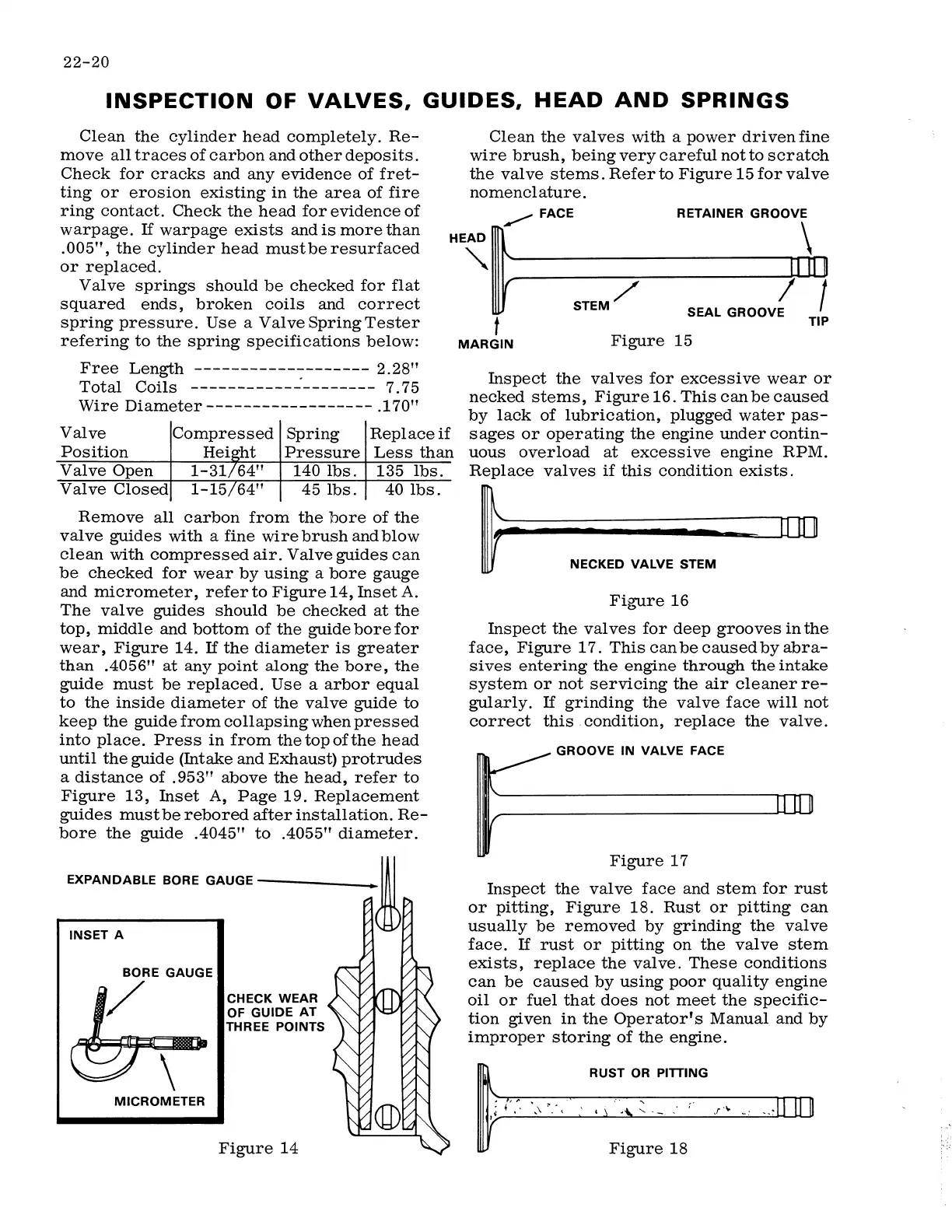
Clean the valves with a power driven fine
wire brush, being very careful not to scratch
the valve stems. Ref er
to Figure 15 for valve
nomenclature.
Clean the cylinder head completely. Re-
move all traces of carbon and other deposits.
Check for cracks and any evidence of fret-
ting or erosion existing in the area of fire
ring contact. Check the head for evidence of
warpage.
If warpage exists and is more than
.005", the cylinder head mustberesurfaced
or replaced.
Valve springs should be checked for flat
squared ends, broken coils and correct
spring pressure. Use a ValveSpringTester
refering to the spring specifications below:
H~t~--F-A_C_E ______ R_E_T_A_I_N-ER_G_R_O_O~V~'~
"" _
ID
□
STEM/ SEAL GROOV( /
Free Length ------------------- 2.28"
Total Coils ___________ _: ________ 7. 75
Wire Diameter------------------ .170"
Valve
Compressed Spring
Replace
if
Position
Heisrht Pressure Less than
Valve Open
1-31/64"
140 lbs.
135 lbs.
Valve Closed
1-15/64"
45 lbs.
40 lbs.
Remove all carbon from the bore of the
valve guides with a fine wire brush and blow
clean with compressed air. Valve guides can
be checked for wear by using a bore gauge
and micrometer, refer to Figure 14, Inset A.
The valve guides should be checked at the
top, middle and bottom of the guide bore for
wear, Figure 14.
If the diameter is greater
than .4056" at any point along the bore, the
guide must be replaced. Use a arbor equal
to the inside diameter of the valve guide to
keep the guide from collapsing when pressed
into place. Press in from the top of the head
until the guide (Intake and Exhaust) protrudes
a distance of .953" above the head, refer to
Figure 13, Inset A, Page 19. Replacement
guides must be rebored after installation. Re-
bore the guide .4045" to .4055" diameter.
EXPANDABLE BORE GAUGE------
INSET A
BORE GAUGE
1/
MICROMETER
CHECK WEAR
OF GUIDE AT
THREE POINTS
Figure 14
t TIP
Figure 15
MARGIN
Inspect the valves for excessive wear or
necked stems, Figure 16. This can be caused
by lack of lubrication, plugged water pas-
sages or operating the engine under contin-
uous overload at excessive engine RPM.
Replace valves if this condition exists.
l;..;;:;;;;;;;;;;;;;;;;;;;;;;;;;;~;;;;;;;:;;;;:===rrDJIIJ[]
r NECKED VALVE STEM
Figure 16
Inspect the valves for deep grooves in the
face, Figure 17. This can be caused by abra-
sives entering the engine through the intake
system or not servicing the air cleaner re-
gularly.
If grinding the valve face will not
correct this . condition, replace the valve.
GROOVE IN VALVE FACE
Figure 17
Inspect the valve face and stem for rust
or pitting, Figure 18. Rust or pitting can
usually be removed by grinding the valve
face.
If rust or pitting on the valve stem
exists, replace the valve. These conditions
can be caused by using poor quality engine
oil or fuel that does not meet the specific-
tion given in the Operator's Manual and by
improper storing of the engine.
RUST OR PITTING
Figure 18
 Loading...