22-23
GRINDING INTAKE AND EXHAUST VALVE SEATS
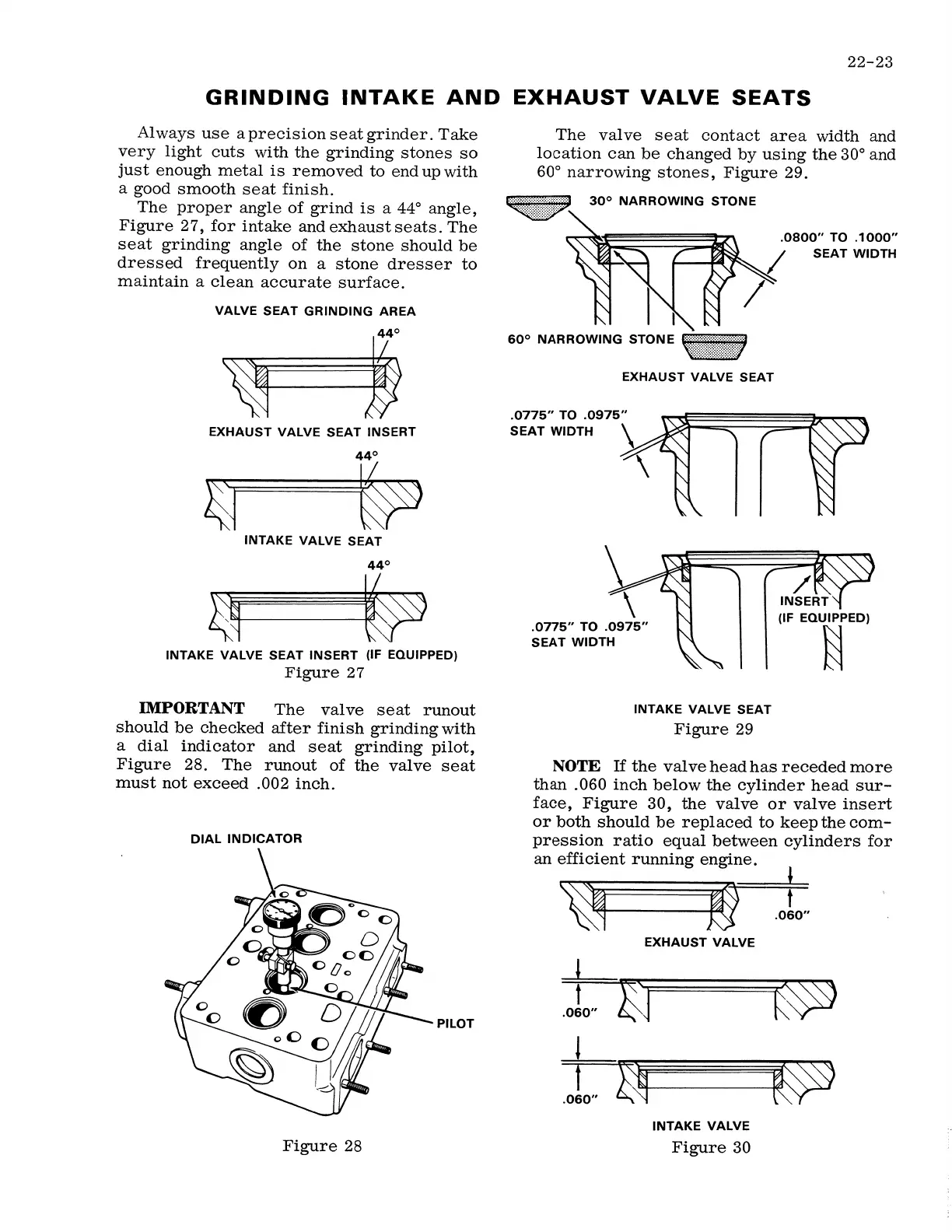
Al ways use a precision seat grinder. Take
very light cuts with the grinding stones so
just enough metal is removed to end up with
a good smooth seat finish.
The proper angle of grind is a 44° angle,
Figure 27, for intake and exhaust seats. The
seat grinding angle of the stone should be
dressed frequently on a stone dresser to
maintain a clean accurate surface.
VALVE SEAT GRINDING AREA
EXHAUST VALVE SEAT INSERT
~
INTAKE VALVE SEAT
44°
~---~
INTAKE VALVE SEAT INSERT {IF EQUIPPED)
Figure 27
IMPORTANT
The valve seat runout
should be checked after finish grinding with
a dial indicator and seat grinding pilot,
Figure 28. The runout of the valve seat
must not exceed .002 inch.
DIAL INDICATOR
PILOT
The valve seat contact area width and
location can be changed by using the 30° and
60° narrowing stones, Figure 29.
••':'.';:;:;:::;;::::>'
30° NARROWING STONE
60° NARROWING STONE,,.,.,, .. ,.,.,:::,.,,,
EXHAUST VALVE SEAT
.0775"
TO
.0975"
SEAT WIDTH \
\
.0775"
TO
.0975"
SEAT WIDTH
INTAKE VALVE SEAT
Figure 29
.0800" TO .1000"
SEAT WIDTH
NOTE
If
the valve head has receded more
than .060 inch below the cylinder head sur-
face, Figure 30, the valve or valve insert
or both should be replaced to keep the com-
pression ratio equal between cylinders for
an efficient running engine.
~
t
.060"
EXHAUST VALVE
l
t
.060"
!
t
.060"
INTAKE VALVE
Figure 28 Figure 30