EasyManuals Logo
Home>Casio>Synthesizer>CTK-5000

Casio CTK-5000 User Manual

Casio CTK-5000
40 pages
To Next Page IconTo Next Page
To Previous Page IconTo Previous Page
Page #16 background imageLoading...
Page #16 background image
– 14
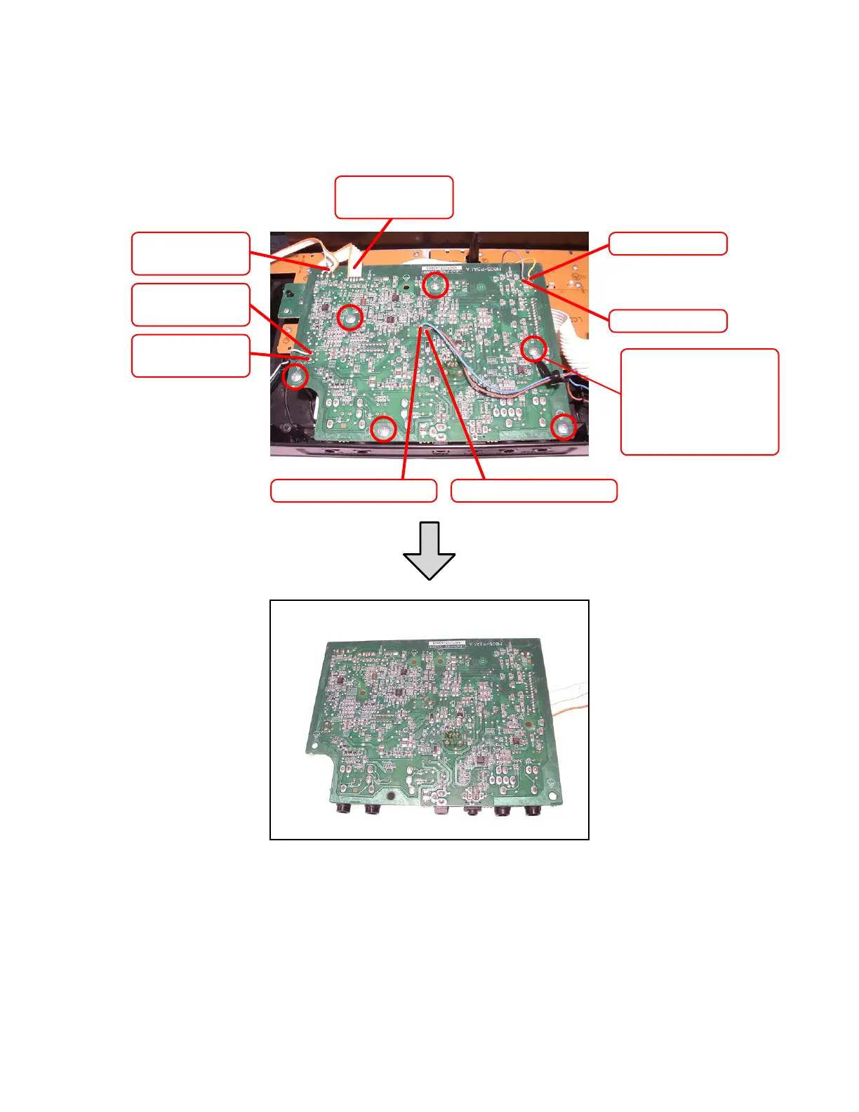
7. To remove the sub PCB (M805-PSA1).
7-1. Remove six screws on the PCB (M805-PSA1).
7-2. Remove two cables by soldering.
7-3. Remove six lead wires by soldering.
7-4. Remove the PCB (M805-PSA1).
Cable (CN7)
(Pitch bend)
Cable (CN12)
(M805-CNB2)
Lead wire (Yellow)
Lead wire (Gray)
Speaker lead wire
(White)
Speaker lead wire
(Green)
Speaker lead wire (Brown)
Speaker lead wire (Blue)
When removing the
screw, be sure NOT to
misplace the components
fixing the speaker lead
wires.

Questions and Answers:

Question and Answer IconNeed help?

Do you have a question about the Casio CTK-5000 and is the answer not in the manual?

Casio CTK-5000 Specifications

General IconGeneral
MIDI-keyboard number of keys61 keys
InterfaceUSB
DC-in jackYes
Dimensions (WxDxH)950 x 376 x 130 mm

Related product manuals