— 5 —
POWER SUPPLY CIRCUIT
The power supply circuit generates seven voltages as shown in the following table. VDD voltage is always
generated. The others are controlled by APO signal from the CPU.
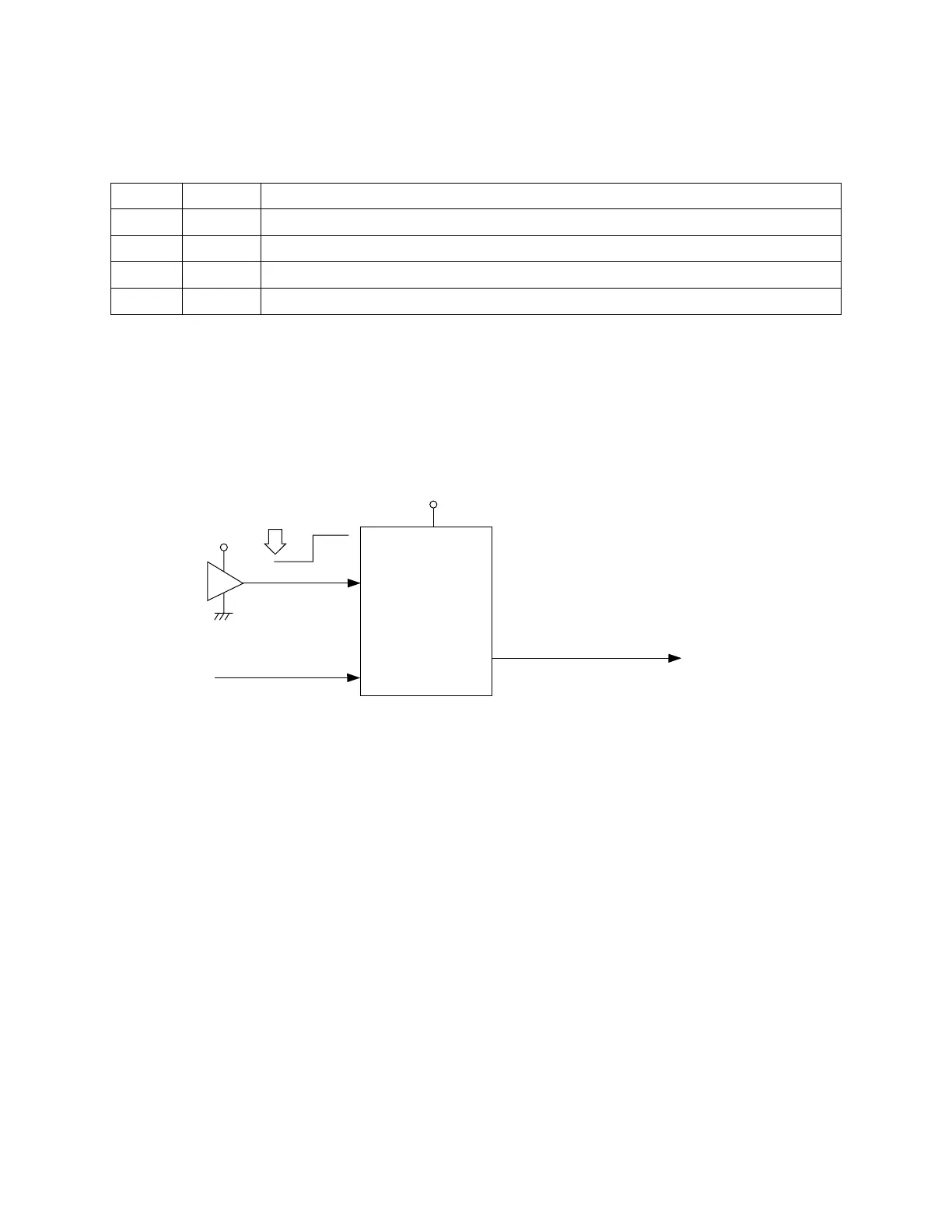
RESET CIRCUIT
When batteries are set or an AC adapter is connected, the reset IC provides a low pulse to the CPU. The
CPU then initializes its internal circuit, and clears the RAM.
When the power switch is pressed, the CPU receives a low pulse of POWER signal. The CPU sends APO
signal to the power supply circuit.
Reset IC
IC6
S-80940AN
To power supply circuit
VDD
Battery set
RESET
VDD
POWER
From power switch
NMI
RSTB
APO
CPU
LSI4
GT913F
SCK0
Name Voltage For operation of
VDD +5 V CPU, Reset IC, Sound source ROM, RAM, Chip selector
DVDD +5.3 V CPU, Sustain jack, MIDI jack, LCD driver
AVDD +5.3 V DAC, Filter
VC +8 V Power amplifier
 Loading...