— 3 —
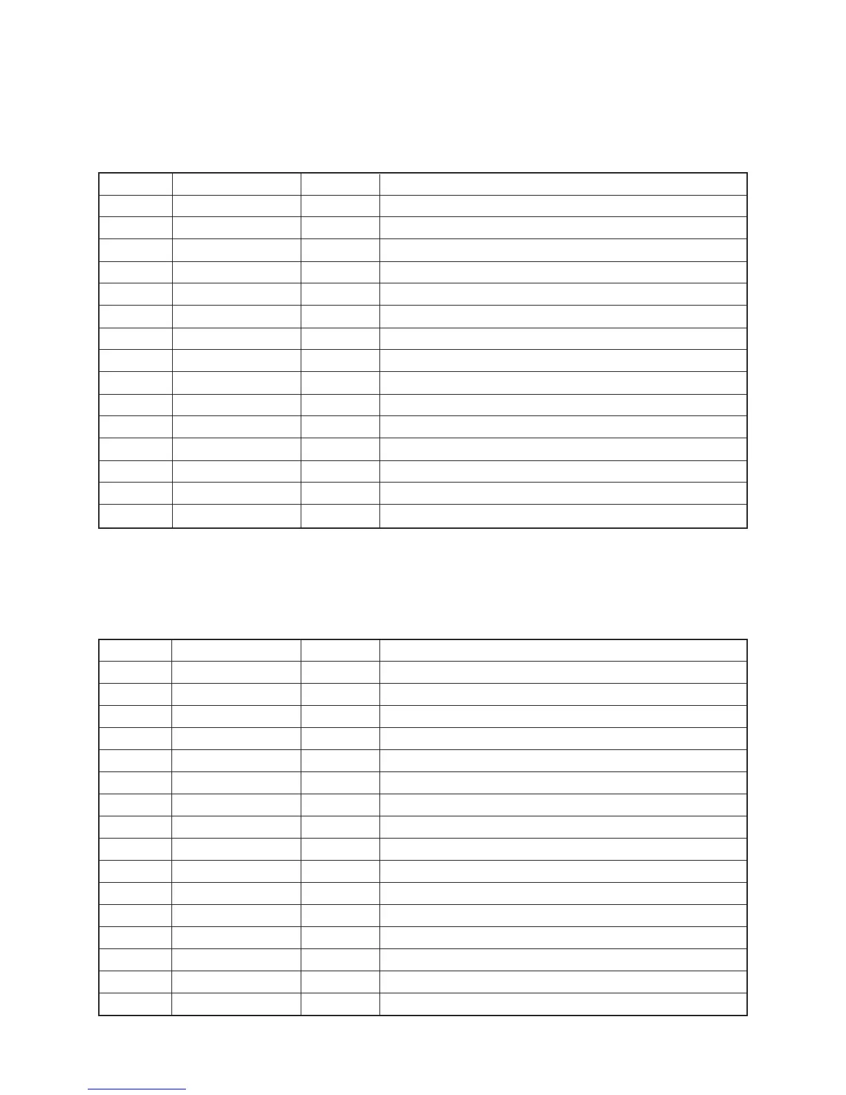
LCD Driver (IC102 : KS0035)
The KS0035 is an LCD driver for a segment type LCD, and it can drive up to 53 segments.
The following table shows the pin functions of IC102.
Pin No. Terminal In/Out Function
1, 2 TEST1, TEST2
—
Not used. Connected to ground.
3 RESET In Power ON reset terminal. On: +5 V Off: 0 V
4 AVDD In +5 V source for the built-in DAC
5 OUT Out Sound waveform output
6 AGND In Ground (0 V) source for the built-in DAC
7 GND In Ground (0 V) source
8 COSI In 21.725 MHz clock pulse input
9 COSO
—
Not used
10 VDD In +5 V source
11 ~ 18 KI0 ~ KI7 In Input terminals from keys and switches
19 KO11 Out Display data output
20 KO10 Out Bit clock output
21 KO9 Out Chip enable signal for the LCD driver
22 KO8 Out Display blanking output
23 ~ 30 KO7 ~ KO0 Out Key scan signal outputs
CPU (LSI101: MSM6387B-A28)
Containing a sound data ROM and a DAC (Digital to Analog Convertor), the CPU provides sound waveform
in accodance with the pressed key and the selected tone.
The following table shows the pin functions of LSI101.
Pin No. Terminal In/Out Function
1 ~ 14 S1 ~ S14 Out Segment output
15 ~ 17 S15 ~ S17
—
Not used
18 ~ 20 S18 ~ S20 Out Segment output
21 ~ 30 S21 ~ S29
—
Not used
31 ~ 47 S30 ~ S46 Out Segment output
36 S35
—
Not used
48 ~ 54 S47 ~ S53
—
Not used
55 OSC In Terminal for the internal clock generator
56 VDD In +5 V source
57 –INH In Display blanking input
58 VLCD In +5 V source for the internal driver
59 VSS In Ground (0 V) source
60 CE In Chip enable input
61 CLK In Bit clock input
62 DATA In Display data input
63, 64 COM1, COM2 Out Common out put
 Loading...