2
4 mm
x 4
1
4 mm
x 4
3
CS 59/79
Z 3585
!
-S/E TABLE
-S/A TABLE EXTENSION
-MESA DE EXTENSION
-U-GR. TISCHVERLANGERUNG
13
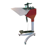
19 mm Wrench
5
!
50 MM
MINIMUM
50 MM BETWEEN
THE SUPPORT OF
FOOT AND THE
GROUND.
ADJUSTMENTS
6
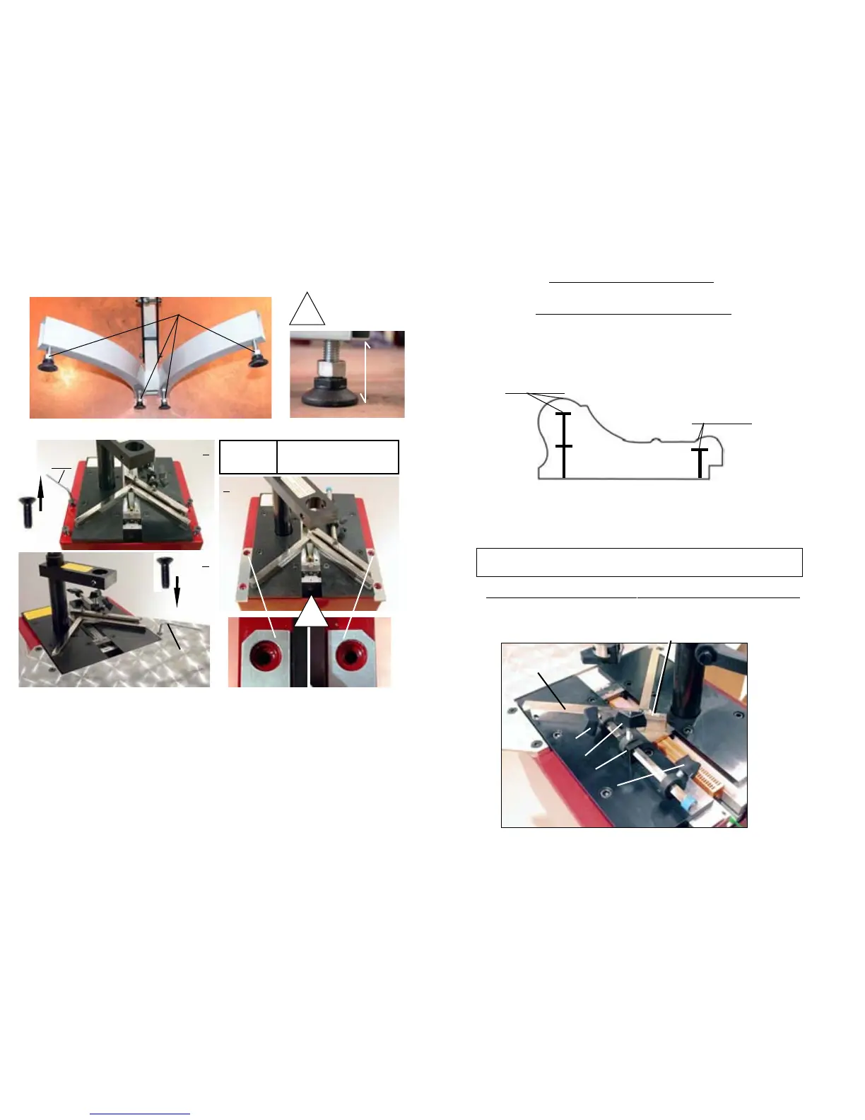
2 mm MINIMUM
2 mm MINIMUM
P 1
P2
P3
B1
90° JOINING ANGLE ASSEMBLY
B
As a general rule a MINIMUM 2 mm clearance (less than 1/8”) above the wedges shall
be respected.
Same sized wedges can be stacked in order to avoid to have to change the cartridge size
when joining frames with different thickness.
AS A GENERAL RULE, THE JOINING MUST BE CARRIED OUT AS
CLOSE TO THE THICKEST MOULDING PART(S) AS POSSIBLE .
SELECTION OF STAPLING POSITIONS
The CS 59 is designed to join mouldings in one or two places (positions) without limitation of the
number of wedges in any of those places. The selection depends on the width and thickness of the
moulding to join.
SETTING AND STORING THE STAPLING POSITIONS
Unlock the stapling position lock handles P1, P2 and P3.
(Approx.1/8’’)
(Approx.1/8’’)