i01228520
Generator Set - Test
SMCS Code: 4450-081
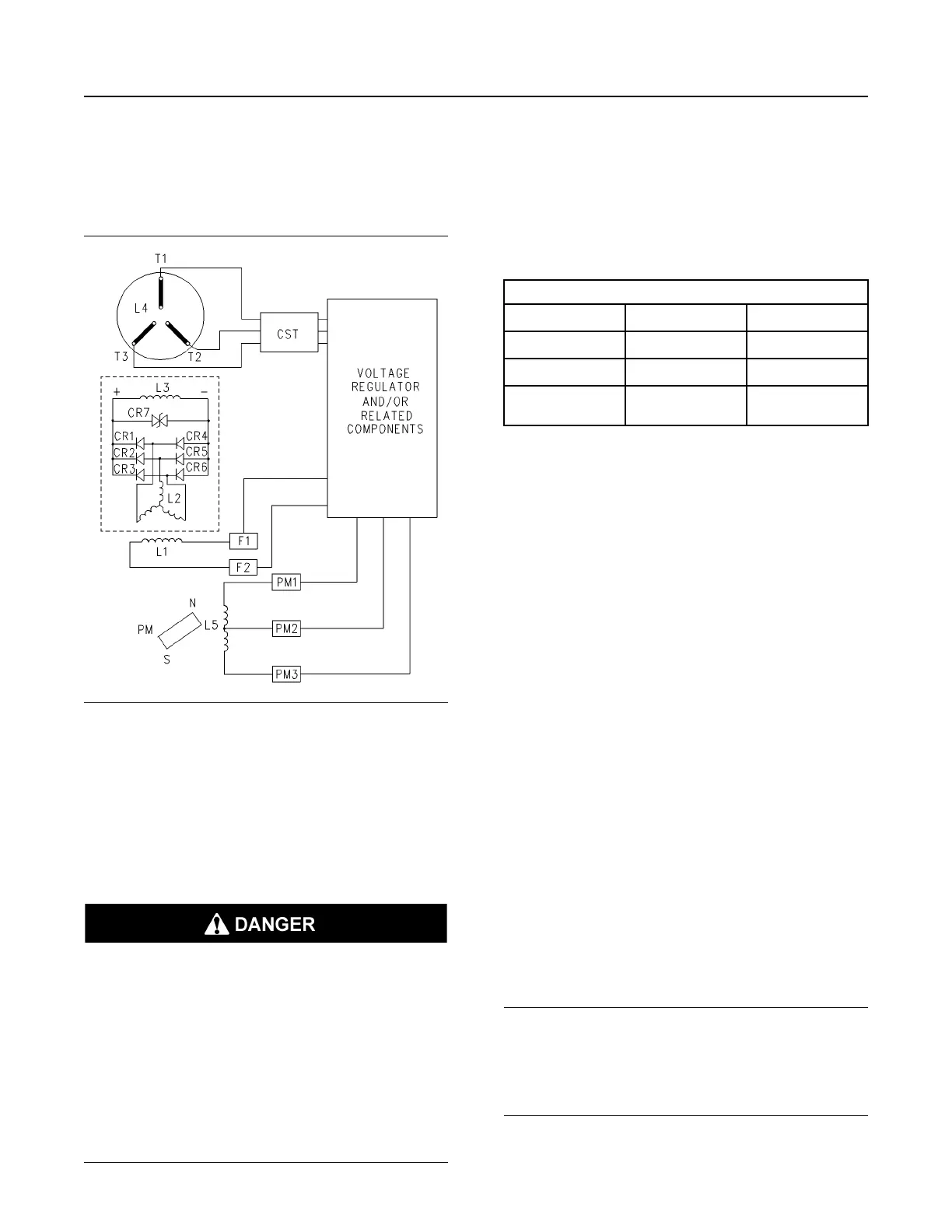
Illustration 117 g00669571
Generator Wiring Diagram
(CR1-CR6) Diodes
(CR7) Varistor
(L1) Exciter field (stator)
(L2) Exciter armature (rotor)
(L3) Main field (rotor)
(L4) Main armature (stator)
(L5) Pilot exciter armature
(PM) Permanent magnet
(RFA) Rotating field assembly
(CST) Customer supplied transformer
Dangerous voltages are present at both the
generator and the system bus.
Under no circumstances should any attempt be
made to connect instrumentation to these points
until you are certain all power is off.
All instruments must be connected to the
generator and the system bus through potential
transformers, which provide a maximum of 600
volts to the instruments.
Failure to follow instructions will result in death
or serious injury.
Dangerous voltages are present at the
generator's output terminals. Until the power is
verified to be OFF, there should not be any device
that is connected to the following terminals: (T1),
(T2) and (T3). The voltmeter must be connected
to the generator through potential transformers.
Potential transformers provide a maximum of 600
volts to the voltmeter.
Table 21
Tools Needed
Part Number Part
Quantity
6V-7070
Digital Multimeter
1
12 VDC battery
1
Potential
Transformer
1
The generator set functional test is a simplified test
that can be performed in order to determine if the
generator is functional. The generator set functional
test should be performed on a generator set that is
under load.
The generator set functional test determines if the
following statements happen:
• A phase voltage is being generated.
• The phase voltages are balanced.
• The phase voltages change relative to engine
speed.
The generator set functional test consists of the
following steps:
1. Stop the generator. Connect the potential
transformer's high voltage winding to the
generator terminals (T1) and (T2). Connect the
voltmeter to the low voltage winding. If two
transformers are available, connect the high
voltage winding of the second transformer to the
generator terminals (T1) and (T3). Connect the
secondary terminals that correspond to generator
terminal (T2) of both transformers together.
2. Disconnect wires “F1+” and “F2-” from the voltage
regulator. Disconnect the generator from the load.
3. Connect a 12 VDC automotive battery to wires “F1
+” and “F2-” .
NOTICE
Do not operate the generator set at a speed that is
higher than one-half of the rated speed.
Higher speeds under these test conditions can cause
damage to the system.
4. Operate the generator set at half the rated speed.
SEBU7125-13
137
Maintenance Section
Generator Set - Test
 Loading...