Generator Set Control (GSC)
Functions and Features of the GSC
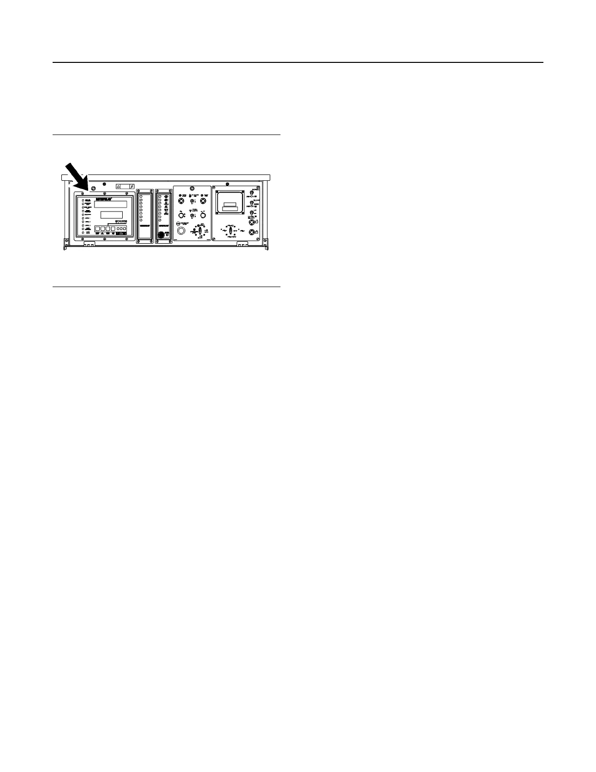
Illustration 49 g00643608
The Location of the GSC on the EMCP II Control
Panel
The left side of the control panel contains the
generator set control (GSC). The GSC is the main
component of the system. The GSC displays
generator output, generator set functions, fault
conditions and key engine parameters. The GSC
accepts information from the following sources:
operator, magnetic pickup, oil pressure sensor, water
temperature sensor and optional remote sources.
This information is used to determine the “ON/OFF”
state of the engine's air, fuel, and starter.
In the very basic operating conditions, the GSC
receives a signal in order to run the generator set.
The GSC turns on the engine's fuel and the engine
starter. When the engine speed reaches the crank
termination speed, the starter is disengaged. When
the GSC receives a signal to stop the engine, the
GSC shuts the fuel off.
The functions of the GSC are listed below.
• The GSC controls the normal starting and
stopping of the engine.
• The GSC shows engine conditions and generator
output information on two displays. The displays
also show fault codes and GSC programming
information.
• The GSC monitors the system for faults. If a fault
occurs, the GSC performs a controlled fault
shutdown or the GSC provides a fault alarm
annunciation. The GSC uses indicators and
displays in order to describe the fault.
• The GSC contains programmable features for
certain applications or customer requirements.
The features of the GSC are listed below.
• Cycle Crank : The GSC can be programmed to
crank for adjustable time periods. For
programming instructions, refer to the Systems
Operation, Testing and Adjusting, SENR5809,
“Electronic Modular Control Panel II (EMCP II) For
MUI Engines” or to the Systems Operation,
Testing and Adjusting, SENR5398, “Electronic
Modular Control Panel II (EMCP II) For EUI
Engines”.
• Governor Control : When the engine oil
pressure increases past the low oil pressure set
point, the GSC indicates that the governor should
increase the engine speed from idle rpm to rated
rpm.
• Cooldown : In order to perform a normal
shutdown upon receiving a signal, the GSC waits
for a preprogrammed time period before shutting
down the engine via the fuel control.
• Automatic Operation : In the automatic mode,
the GSC can be started by a remote signal
(contact closure). Upon loss of the signal (contact
opening), the GSC will perform a normal
shutdown.
• Alarm Module Communication : The GSC can
transmit the fault and alarm conditions to an alarm
module (AM).
• Power Down: The EMCP II system is designed
to remove power from the GSC when the engine
control switch (ECS) is in the OFF/RESET mode
and when the proper jumper wire is removed. The
GSC will not allow the power down until the crank
termination relay and the fuel control relay are
turned off for about 70 seconds. The GSC remains
powered, if the wire is not removed. For the wiring
diagram and the location of the jumper wire, refer
to the Systems Operation, Testing and Adjusting,
SENR5809, “Electronic Modular Control Panel II
(EMCP II) For MUI Engines” or to the Systems
Operation, Testing and Adjusting, SENR5398,
“Electronic Modular Control Panel II (EMCP II) For
EUI Engines”.
• Fuel Solenoid Type : The GSC can be
programmed to work with an energized to run
(ETR) fuel system or to work with an energized to
shutdown(ETS) fuel system.
38
SEBU7125-13
Operation Section
If Equipped
 Loading...