Application and Installation Guide EMCP 4 SCADA Data Links
©2013 Caterpillar
All rights reserved. Page 6
2.2 WIRING
The RS-485 SCADA data link uses galvanically isolated half-duplex communications. It requires two
twisted conductors (Rx/Tx+ and Rx/Tx-) and one reference or common conductor (REF). It is
recommended to use a third conductor for the reference, instead of the shield. Therefore the RS-485
SCADA Data Link requires three conductors, plus a shield. See Table 2-1 for the pins on the EMCP 4.2,
and Table 2-2 for the pins on the EMCP 4.3 and 4.4.
T
ABLE 2-1: RS-485 SCADA PINOUT ON EMCP 4.2
Pin # Name Description
3 MB- RS-485 differential inverting line (Rx/Tx-) (A)
4 MB-REF RS-485 reference signal
5 MB+ RS-485 differential non-inverting line (Rx/Tx+) (B)
TABLE 2-2: RS-485 SCADA PINOUT ON EMCP 4.3 AND 4.4
Pin # Name Description
90 MB- RS-485 differential inverting line (Rx/Tx-) (A)
101 MB-REF RS-485 reference signal
100 MB+ RS-485 differential non-inverting line (Rx/Tx+) (B)
Proper implementation of Modbus on EMCP 4 requires 3 conductors, plus a shield. Using a 2-wire
unshielded cable is not recommended; however, if needed for low-noise environments and short
distances, connect MB+ and MB- only. In cases where noise is present on the shield, improved
performance may be achieved by not using the shield as a Reference. Refer to the Shielding section
below.
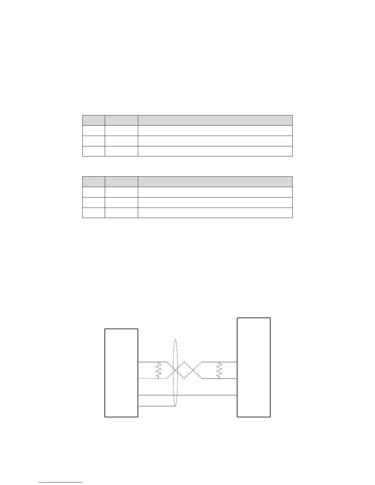
Figures below show connections to half-duplex (also called 2-wire, Figure 2-3) and full-duplex (also called
4-wire, Figure 2-4) devices.
NOTE: Consult device documentation to verify wiring requirements.
F
IGURE 2-3: POSSIBLE WIRING TO HALF-DUPLEX RS-485 DEVICE
Half
Duplex
RS-485
Device
EMCP
RS-485
SCADA
Tx/Rx+
(B)
Tx/Rx-
(A)
120 120
REF (or
GND)
MB-
MB-REF
MB+
BATT-
 Loading...