EasyManua.ls Logo

Catalyst 2960-XR - User Manual

Catalyst 2960-XR
6 pages
Print Icon
To Next Page IconTo Next Page
Loading...
Power Supply Installation
This chapter applies only to the Catalyst 2960-XR switches. It contains these topics:
Power Supply Module Overview, on page 1
Installation Guidelines, on page 4
Installing or Replacing an AC Power Supply, on page 5
Finding the Serial Number, on page 6
Power Supply Module Overview
The switch operates with either one or two active power supply modules. You can use two AC modules, or
one module and a blank cover.
The Catalyst 2960XR-48FPD-I and 2960XR-48FPS-I only support the PWR-C2-1025WAC power supply.
You cannot use the PWR-C2-250WAC and PWR-C2-640WAC power supplies in these switches.
Note
Table 1: Power Supply Model Numbers and Description
DescriptionPart Number
250-W AC power supply modulePWR-C2-250WAC=
640-W AC power supply modulePWR-C2-640WAC=
1025-W AC power supply modulePWR-C2-1025WAC=
The 250-W and 640-W AC power supply modules are autoranging units that support input voltages between
100 and 240 VAC. The 1025-W power supply module is an autoranging unit that supports input voltages
between 115 and 240 VAC. All power supply modules have internal fans. All switches ship with a blank
cover in the second power supply slot.
Each AC power supply module has a power cord for connection to an AC power outlet.
Power Supply Installation
1
Question and Answer IconNeed help?

Do you have a question about the Catalyst 2960-XR and is the answer not in the manual?

Summary

Power Supply Module Overview

Power Supply Models

Lists AC power supply models, their part numbers, and descriptions, including compatibility notes.

Installation Guidelines

LED Status Indicators

Details the meaning of AC OK and PS OK LED states for power supply modules.

Safety and Handling Precautions

Provides essential cautions and warnings for installing and removing power supply modules safely.

Installing or Replacing an AC Power Supply

Installation Procedure

Step-by-step instructions for removing and installing AC power supply modules, including notes and warnings.

Finding the Serial Number

Serial Number Location

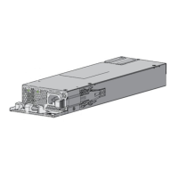
Illustrates where to find the serial number on 1025-W and 250/640-W AC power supply modules.

Overview

This document provides comprehensive information regarding the installation and maintenance of power supply modules for the Catalyst 2960-XR switches. It covers the power supply module overview, installation guidelines, procedures for installing or replacing AC power supplies, and instructions for locating the serial number.

Power Supply Module Overview

The Catalyst 2960-XR switches are designed to operate with either one or two active power supply modules. Users have the flexibility to configure the switch with two AC modules or with one module and a blank cover. It is important to note that the Catalyst 2960XR-48FPD-I and 2960XR-48FPS-I models specifically support only the PWR-C2-1025WAC power supply. The PWR-C2-250WAC and PWR-C2-640WAC power supplies are not compatible with these particular switch models.

The available power supply modules include the PWR-C2-250WAC=, PWR-C2-640WAC=, and PWR-C2-1025WAC=. Each of these modules serves as an AC power supply. The 250-W and 640-W AC power supply modules are autoranging units, capable of supporting input voltages ranging from 100 to 240 VAC. Similarly, the 1025-W power supply module is also an autoranging unit, designed to support input voltages between 115 and 240 VAC. All power supply modules are equipped with internal fans to ensure proper cooling. By default, all switches are shipped with a blank cover installed in the second power supply slot. Each AC power supply module comes with its own power cord for connection to an AC power outlet.

The power supply modules feature several key components for user interaction and status monitoring. These include an AC OK LED, a PS OK LED, an AC power cord retainer, an AC power cord connector, a release latch, and the power supply unit itself. For instance, on the PWR-C2-1025WAC power supply, the AC OK LED and PS OK LED provide visual status indications. The AC power cord retainer helps secure the power cord, while the release latch facilitates easy removal and installation of the module. The PWR-C2-640WAC and PWR-C2-250WAC power supplies share similar component layouts and functionalities.

If a power supply slot is not occupied by a power supply module, it is crucial to install a power supply slot cover. These covers, equipped with release handles and retainer clips, are essential for maintaining proper airflow and preventing the ingress of dust and other contaminants.

Power Supply Status LEDs

The power supply modules are equipped with two status LEDs: AC OK and PS OK. These LEDs provide immediate visual feedback on the operational status of the power supply.

  • AC OK LED:

    • Off (AC LED is off): Indicates that there is no AC input power.
    • Green: Signifies that AC input power is present.
  • PS OK LED:

    • Off: Indicates that the output is disabled, or the input voltage is outside the operating range.
    • Green: Shows that power output is being supplied to the switch.
    • Red: Alerts the user that the power output has failed.

Installation Guidelines

Adhering to specific guidelines is critical when removing or installing a power supply module to ensure the proper functioning of the switch and the safety of the user.

  • Avoid Forcing: Never force the power supply module into the slot. Doing so can damage the pins on the switch if they are not correctly aligned with the module.
  • Secure Connection: A power supply that is only partially connected to the switch can disrupt the system's operation. Ensure a firm and complete connection.
  • Power Down Before Removal/Installation: Always remove power from the power-supply module before attempting to remove or install it.
  • Hot-Swappable: The power supply is hot-swappable, meaning it can be replaced without powering down the entire switch, provided the other guidelines are followed.

Safety Precautions:

  • Empty Slot Caution: Do not operate the switch with one power-supply module slot empty. Both module slots must be populated with either a power supply or a blank module to ensure proper chassis cooling.
  • Faceplates and Covers: Blank faceplates and cover panels serve three important functions: they prevent exposure to hazardous voltages and currents inside the chassis, contain electromagnetic interference (EMI) that might disrupt other equipment, and direct the flow of cooling air through the chassis. Never operate the system unless all cards, faceplates, front covers, and rear covers are securely in place.
  • Avoid Reaching into Vacant Slots: Do not reach into a vacant slot or chassis while installing or removing a module. Exposed circuitry can pose an energy hazard.
  • Qualified Personnel: Only trained and qualified personnel are authorized to install, replace, or service this equipment.
  • External Power System: If a Cisco external power system is not connected to the switch, install the provided connector cover on the back of the switch.

Installing or Replacing an AC Power Supply

The process for installing or replacing an AC power supply involves several steps to ensure safety and proper functionality.

  1. Turn Off Power: Begin by turning off the power at its source.
  2. Remove Power Cord: Disconnect the power cord from the power cord retainer, then remove it from the power connector.
  3. Remove Old Power Supply: Press the release latch on the right side of the power supply module inward and slide the power supply out of the slot.
    • Note: Do not leave the power-supply slot open for more than 90 seconds while the switch is operating.
    • Warning: If the unit has multiple power supply connections, all connections must be removed to de-energize the unit completely.
  4. Insert New Power Supply: Insert the new power supply into the power-supply slot and gently push it in until it is fully seated. When correctly inserted, the 250-W and 640-W power supplies (excluding the power cord retainer) will be flush with the switch's rear panel. The 1025-W power-supply module will extend slightly from the switch's rear panel.
  5. Optional: Secure Power Cord: (Optional) Create a loop in the power cord and thread it through the power cord retainer to secure it.
  6. Connect Power: Connect the power cord to the power supply and then to an AC power outlet. Turn on the power at the source.
  7. Verify LEDs: Confirm that both the AC OK and PS OK LEDs on the power supply are green, indicating proper operation.
  8. Install Second Power Supply: If applicable, repeat these steps to install a second power supply.
    • Note: When installing the second power supply, the LEDs on the power supply might blink momentarily.

Finding the Serial Number

The serial number of the switch is crucial for contacting Cisco Technical Assistance. It can be found on the power supply module itself or by using the show version privileged EXEC command. For the 1025-W AC power supply, the serial number is typically located on a label on the module. Similarly, for the 250-W and 640-W AC power supply modules, the serial number is also found on a label on the unit.

Catalyst 2960-XR Specifications

General IconGeneral
ModelCatalyst 2960-XR
Uplink Interfaces4 x 1G SFP or 2 x 10G SFP+
Operating SystemCisco IOS
Form FactorRack-mountable
MAC Address Table Size16, 000 entries
Ports24 x 10/100/1000 Ethernet ports
StackingYes, FlexStack-Plus
Power SupplyOptional redundant power supply
Layer SupportLayer 2
Product TypeSwitch
Operating Temperature0 to 45°C (32 to 113°F)
Weight4.5 kg