low voltage
3990A640 REV B
NOV 2014
QAT Guide
Page 1
Auxiliary Products
The programmable time switch can be used to automatically control
pool pumps, lights, geysers, etc.
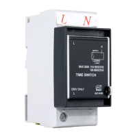
QAT-TRDM – ELECTRONIC TIME SWITCH
Installation and Programming Guide
General
1. During a power failure, the symbol is displayed and the time
switch enters standby.
2. The time switch has a backup power feature which requires
30 minutes to charge.
Important Notes
1. Isolate supply power before installing time switch.
2. Install the time switch on either mini rail or DIN rail (remove the escutcheon clip for DIN).
3. Connect the time switch according to Figure 1 or Figure 2.
Use a suitable contactor (Figure 3) if necessary to switch higher current.
Observe markings for Line and Neutral poles.
4. Apply power and set the time and desired program schedule (see overleaf).
Installation
Technical Data
Parameter Specication
Supply Voltage 230 VRMS 50 Hz, 1Ph
Maximum Load Resistive (Geysers, under oor heating, lights) 21 A
Inductive (Pool pump, air conditioners) 10 A
Contact Endurance 25 000 (minimum) Operations
Degree of Ingress Protection IP41(not waterproofed)
Operating Temperature -20 °C to +55 °C
Single Segment Period 15 min.
Maximum Period for all Segments 96 x 15 min. Segments
Clock Accuracy ± 3 min. per month
Time Retention (Power Outage) 24 h
Figure 1: DB wiring Figure 2: Stand alone wiring Figure 3: Wiring a contactor for loads
greater than 21 A resistive or 10 A inductive
L N
Load
L N
L
L N
Time
Switch
Neutral
Bar
Load
L N
L
L N
Time
Switch
L N
L N
L
Time
Switch
Coil
Load
L1 L2 L3
T1 T2 T3
Contactor
Supply
L N
3. In the event of a power failure, a fully charged time switch will keep time for up to 24 hours.
The programmed schedule is always retained.
4. CBIadvisesthatthetimeswitchbeinstalledbyasuitablyqualiedperson.