MANUAL LOADER CHAPTER 6
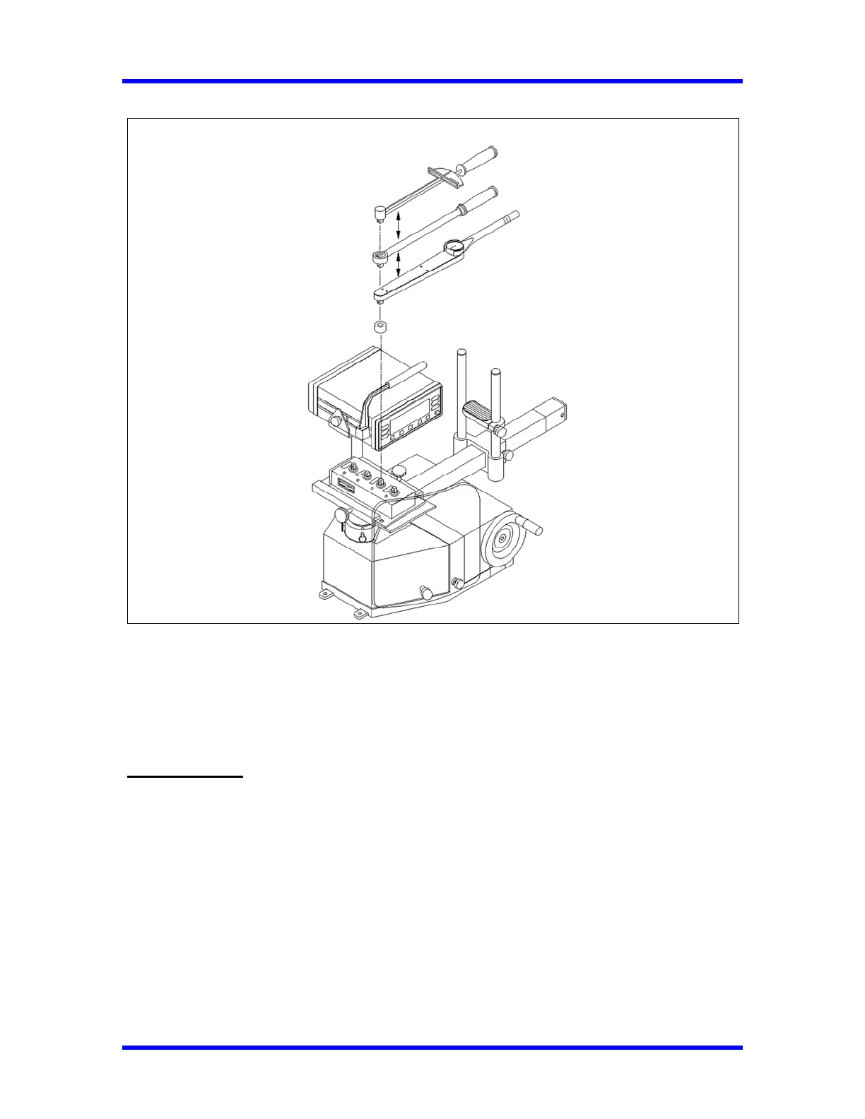
Figure 6-2 Set up for Dial indicating, Deflection Beam and Micro-Adjustable Torque Wrenches.
1- Transducer Mounting
A transducer facilitates the low-to-high ranges of the wrench under test. The transducer must be
installed into the loader by lining up the red mark and securing it using two quick release pins.
IMPORTANT
The connector on single transducer cables contains the EEPROM calibration memory
chip. Never attempt to remove the connector from the transducer.
2- Hand Crank
Turn hand crank on the loader to apply torque.
3- Reaction Slide Assembly’s
The reaction slide is positioned so that the reaction pins straddle the wrench handle at the hand
hold position specified on the wrench.
6-4