3. Now with the main board removed, you can begin by identifying the locations where you will
need to connect your wires. See the images below for the locations, as well as a pinout
reference from the CD-i Service manual.
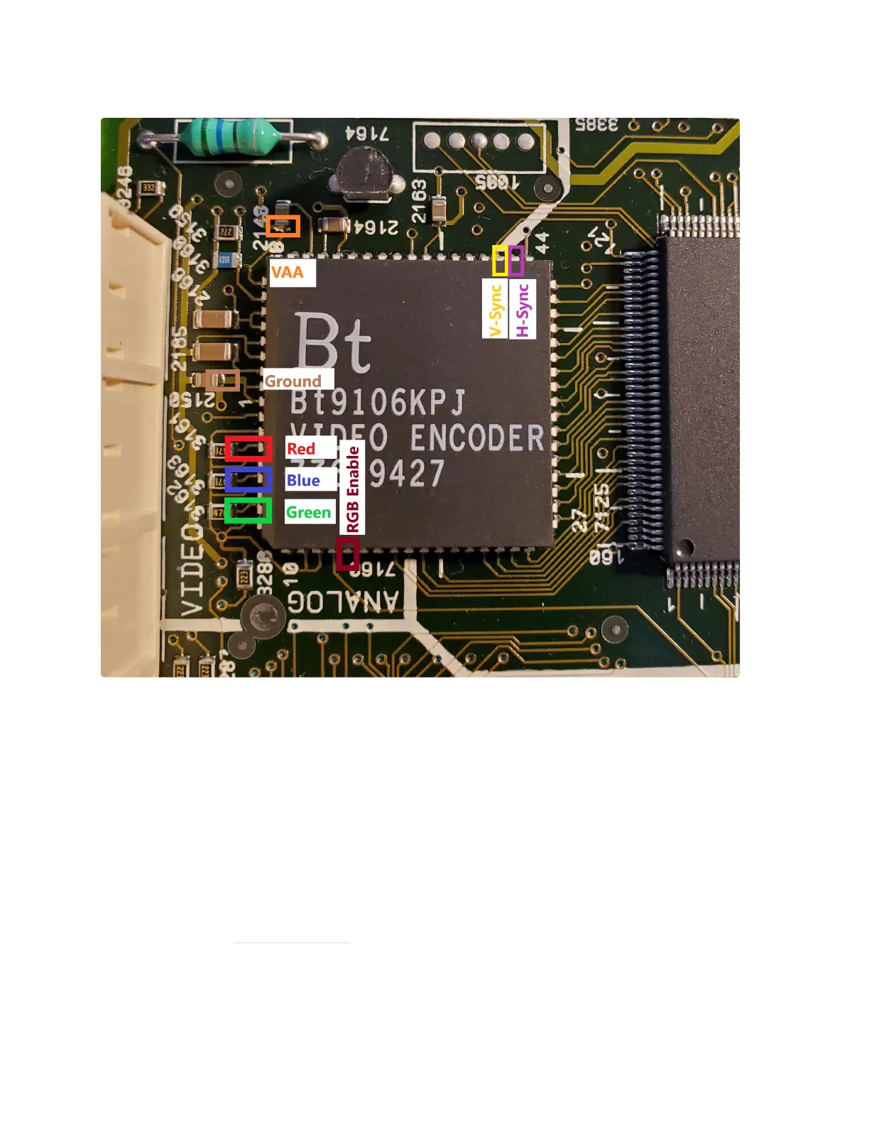
Note the locations of the signals you will need to tap.
Red = Pin 4
Blue = Pin 6
Green = Pin 8
RGB Enable = Pin 14
V-Sync = Pin 46
H-Sync = Pin 45
Ground = Pin 1
VAA = Pin 66 or 65
Important Note: On some models the capacitor shown for connecting VAA is backwards.
Connecting this backwards will not cause damage, but the RGB board will not work. Verify that
the side of the capacitor you are connecting to is connected to Pin 66 or 65 and not Ground.
Special thanks to Simon Laroche for pointing this out!
 Loading...