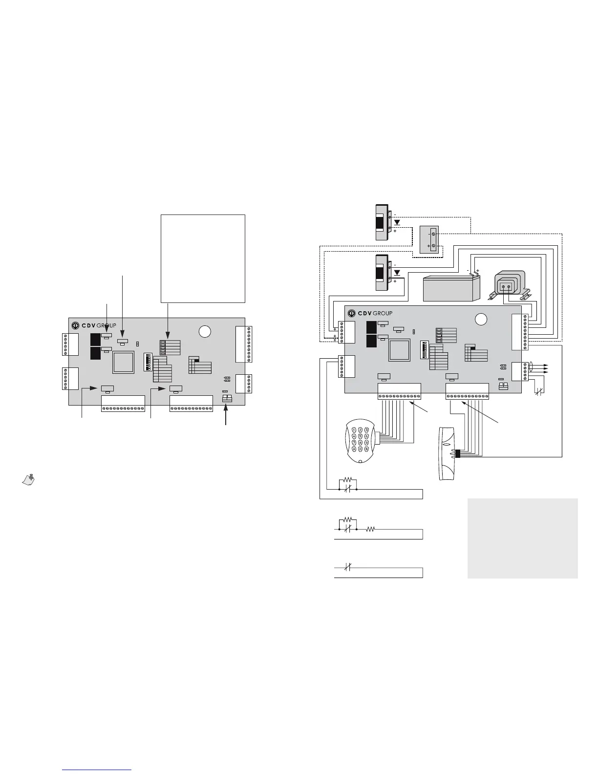
Figure 6: Connection drawing of the CA-A470-AFigure 5: CA-A470-A indicators
Warranty
Paradox Security Systems Ltd. (“Seller”) warrants its products to be free from defects in materials and workmanship under normal use for a period of one year. Except as spe-
cically stated herein, all express or implied warranties whatsoever, statutory or otherwise, including without limitation, any implied warranty of merchantability and tness for
a particular purpose, are expressly excluded. Because Seller does not install or connect the products and because the products may be used in conjunction with products not
manufactured by Seller, Seller cannot guarantee the performance of the security system and shall not be responsible for circumstances resulting from the product’s inability to
operate. Seller obligation and liability under this warranty is expressly limited to repairing or replacing, at Seller’s option, any product not meeting the specications. Returns
must include proof of purchase and be within the warranty period. In no event shall the Seller be liable to the buyer or any other person for any loss or damages whether direct
or indirect or consequential or incidental, including without limitation, any damages for lost prots stolen goods, or claims by any other party, caused by defective goods or
otherwise arising from the improper, incorrect or otherwise faulty installation or use of the merchandise sold. Notwithstanding the preceding paragraph, the Seller’s maximum
liability will be strictly limited to the purchase price of the defective product. Your use of this product signies your acceptance of this warranty.
BEWARE: Dealers, installers and/or others selling the product are not authorized to modify this warranty or make additional warranties that are binding on the Seller.
© 2006 CDVI. All rights reserved.
Centaur is a trademark or registered trademark of CDVI or its afliates in Canada, the United States and/or other countries.
The reader LEDs can be used to verify the reader’s connections and programming. If no ashing occurs when a card
is presented to the reader, the reader may be installed incorrectly. A short ash indicates that the reader is correctly
installed, but the card is the wrong type or that the reader was incorrectly programmed.
24VDC 24VDC Power Supply
(Optional connection method)
V-
V+
V-
LOCK 2
KEYPAD 2
(BCD)
16V Transformer
40VA
Gell Cell BAttery
12V, 7 Ah
E-BUS :
To CT-V900 or to
other CA-A470-A
E-BUS
Connect to tamper
switch (N.C.)
Terminals for
KEYPAD 2
See inputs in Centaur Software
manual: setting ATZ 2R Connection
Input 1
1KΩ
1KΩ
1KΩ
OR
EOL
Z
COM
OR
Z
COM
See inputs in Centaur Software
manual: setting ATZ 3R Connection
See inputs in Centaur Software
manual: setting NC Input Connection
Reader and keypad wiring may differ
from the diagram. Please consult
your dealer for details.
Terminals for KEYPAD 1
READER 1
BROW N
RED
ORAN GE
YELL OW
WHIT E
GREE N
BLAC K
RED
YELL OW
BROW N
WHIT E
GREE N
BLUE
ORAN GE
BLAC K
12VDC
LOCK 1
+
SP
+12V
R1/KPD
R1/KPC
R1/KPB
R1/KPA
OUT2
OUT1
R1/D1
R1/D0
R1/0V
R1/+5V
SP
+12V
R2/KPD
R2/KPC
R2/KPB
R2/KPA
OUT4
OUT3
R2/D1
R2/D0
R2/0V
R2/+5V
AC
AC
BAT+
BAT-
V+
V+
V-
V-
OUT6
OUT6
A+
B-
GND
TAMPER
TAMPER
D1NC
COM
D1NO
D2NC
COM
D2NO
Z1
COM
Z2
Z3
COM
Z4
CA-A470-A
LOCK #1
AC O K
EOL
BACK UP
SWIT CH
ADD 1
SW1
ADD 2
SW2
L1En erg ize
SW3
L2En erg ize
SW4
BACK UP1
SW5
BACK UP2
SW6
PULSE 5&6
SW7
N/D
SW8
READER#1
DATA
READER#2
DATA
NO C ARD
LOW HI GH
TX RX
E-BU S
B-
A+
2 CA RDS
ALL C ARD S
UNLO CK DOOR
2
0
0
1
1
1
0
1
0
1
AUX OK
COMM
CHEC K B ATT
BATT TR BL
LOCK #2
STATUS
JP120
350mA/700mA
ON
1 2 3 4 5 6 7 8
Green “READER#2 DATA” and “READER#1 DATA” LED:
Long ash = Receiving card read
Short ash = Receiving card read, but the system
does not recognize the card’s format
OFF = Not receiving card read
Green “AC” LED:
ON = AC power
OFF = Power failure
Green “AUX” LED:
ON = Auxiliary power
OFF = Auxiliary power failure
Red “COMM” LED:
ON = Communication failure
OFF = OK
Green “CHECK BATT” LED:
ON = Battery verication in
progress (every minute)
Red “BATT TRBL” LED:
ON = Battery low or disconnected
Green “STATUS” LED:
Flash = Module OK
Slow ash = Communication failure
(see also “COMM” LED)
Green “LOCK#1” and “LOCK #2” LEDs:
ON = Relay activated.
Red “TX” LED and green “RX” LED:
ON = Communication OK (may icker)
OFF = Communication failure
Warning
2-Door Expansion Module (CA-A470-A)
16Vac Transformer Only
The use of a transformer with a rating other 16Vac
can severaly damage the module.
Firmware Requirements
The 2-Door Expansion Module can only be used
with CT-V900-A rmware version R2-C3-05 or higher.
Software Requirementrs
The 2 -Door Expansion Module can only be used
with Centaur version 3.0 build 400 or higher.
 Loading...