Do you have a question about the CDVI ATRIUM ADH10 and is the answer not in the manual?
Contact information and hours for technical assistance.
Guidelines for choosing a suitable installation location and cabinet dimensions.
Instructions for installing tamper switches to detect cabinet opening or removal.
Procedure for installing the lock to secure the ADH10 controller box.
Steps for mounting the ADH10 controller enclosure to the wall.
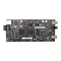
Instructions for securing the ADH10 controller PCB within the enclosure.
Details on connecting external gateways and modules via RS485.
Wiring procedures for connecting door and wall tamper switches to the controller.
Instructions for connecting the AC/DC power supply and indicators.
Information on replacing the AC terminal fuse and its specifications.
Guidance on connecting and managing the 12Vdc battery backup.
Explanation of the status LEDs on the ADH10 controller PCB.
Diagram illustrating the overall system architecture and connectivity.
| Number of Doors | 1 |
|---|---|
| Number of Readers | 2 |
| REX Input | 1 |
| Door Contact Input | 1 |
| Auxiliary Inputs | 2 |
| Lock Output | 1 |
| Maximum Number of Users | 10, 000 |
| Housing Material | Plastic |
| IP Rating | IP30 |
| Relay Output | 1 |
| Power Supply | 12-24V DC |
| Reader Type | Wiegand |
| Auxiliary Outputs | 1 |
| Communication | RS485 |
| Humidity | 0 to 95% (non-condensing) |
| Current Consumption | 150mA |
| Operating Temperature | -20°C to +55°C (-4°F to +131°F) |