EasyManua.ls Logo

CDVI PROMI500 User Manual

CDVI PROMI500
9 pages
To Next Page IconTo Next Page
Page #1 background imageLoading...
Page #1 background image
PROMI500
PIN Code and/or Badge
STAND-ALONE PROXIMITY SYSTEM
WIRING DIAGRAM AND INSTRUCTIONS
3
2
V
1
E
M
B
O
C
T
5
RL1
RL2
3
2
1
ST1
ST2
1
3
I1
PB1
V1
Input voltage
12V ~ or =
230V~
strike
12
V
1
4
5
3
2
Wiring diagram
PCB front view
This device comes with a varistor.
The varistor must be connected on the strike terminal
(electromagnet…) operated by the device.
If this product operates more than one strikes, each of them
should have a varistor.
The varistor controls the overload produced by the strike coil
back emf.
B
Request-to-exit PB1
E
Alarm Input
M
Common PB1, E and 4
O
Relay 1 contact
C
Common
T
Relay 2 N/O contact
I1
Anti-tamper switch
V1
Varistor
ST1
ST2
Jumper for reset
Jumper for relay 1
RL1
Door relay
RL2
Alarm relay
12
Power supply
V
Power supply
1
Data
2
Buzzer
3
Green LED
4
Common M
5
Red LED
Auxiliary reader
(terminal connections)
Warning
Do not use a
switching
power supply
because of the
interference
radiation that
may disturb
the reading of
the badges
N/C contact RL1 (magnet)
N/O contact RL1 (strike)
See wiring diagram auxiliary reader
ST2
1
3
1
3
If you are using a « Shear Lock » electromagnetic lock, it is recommended to use a
separate power supply than the one connected to the PROMI500.
Question and Answer IconNeed help?

Do you have a question about the CDVI PROMI500 and is the answer not in the manual?

CDVI PROMI500 Specifications

General IconGeneral
ModelPROMI500
TypeIP Access Controller
ConnectivityEthernet
Power Supply12V DC
Operating Voltage12V DC
Current Consumption500 mA
Operating Temperature-10°C to +55°C
Humidity10% to 90% non-condensing
IP RatingIP30
Number of Doors Controlled2
Number of Inputs4
User Capacity10, 000
CommunicationTCP/IP
Number of Outputs2
Communication ProtocolsWiegand, OSDP
Supported Card TechnologiesDESFire
Number of Readers Supported2 (Wiegand or OSDP)

Summary

Wiring Diagram

Technical Features

Default Values

Lists the factory-set master code, relay delay, and keypad settings.

Audible Signals

Explains the audio feedback for data validation and mode entry/exit.

Visual Signals

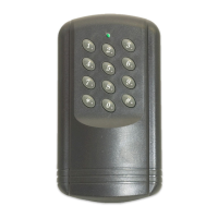
Describes the LED indicators for normal and programming modes.

System Configuration

Setting a New Master Code

Guides on changing the primary access code for programming.

Setting the Mode and Time Outputs

Configures operating modes and door/alarm relay time delays.

Setting New PIN Codes and Badges

Describes the process for adding new user PINs and proximity badges.

User Management and Reset

Deleting or Replacing Badges and PIN Codes

Explains how to remove or update existing user credentials.

Reset Master Code and PINs/Badges

Details the procedure for factory resetting system codes and badges.

Operating Instructions

Provides guidance on how to use the system in different operational modes.

Alarm Function

Auxiliary Reader Wiring

Related product manuals