QUICK START
INSTALLATION GUIDE
www.cdvigroup.com
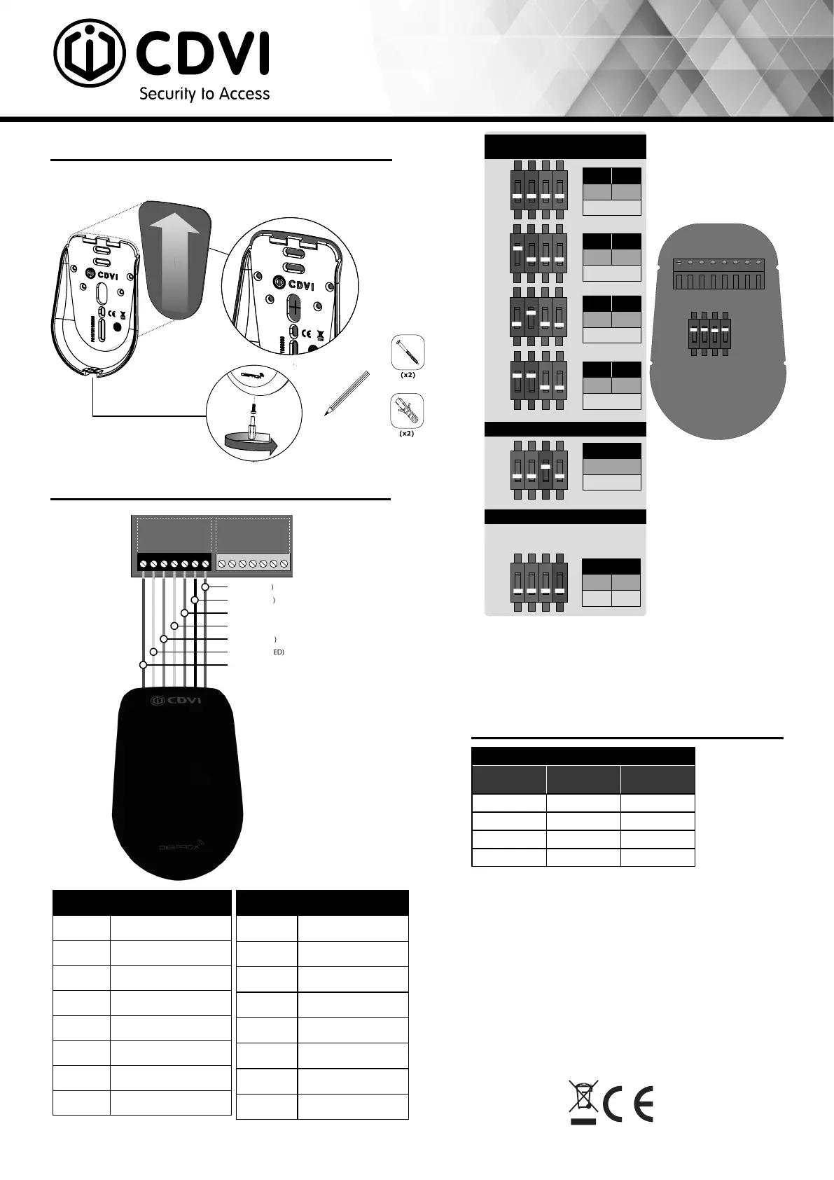
WIRING DIAGRAM
LED STATUS INDICATORS
MOUNTING
All the information contained within this document (pictures, drawing, features, specications and dimensions) could be perceptibly dierent and can be changed without prior notice.
CDVI_SOLARPB-SOLARPW_QS_02_FR-EN_A4_B - G0801FR0007V01 - June 2021
CDVI SAS
31 avenue du Général de Gaulle
93500 PANTIN
01 48 91 01 02
Cable
Red Input voltage 12Vdc
Black 0V
Blue Clock
Green Data 0
White Data 1
Brown Buzzer input
Yellow Green LED input
Orange Red LED input
Terminal block (8 points)
+ Input voltage 12Vdc
- 0V
H Clock
D0 Data0
D1 Data1
B Buzzer
V Green LED
R Red LED
Input LED management
Green LED Red LED Status
OFF OFF O
OFF ON red
ON OFF green
ON ON blue
Card Swiped (DIP3 = ON)
- Badge recognized: the orange LED
illuminates and the buzzer activates for
150 milliseconds.
3
ON
Standard
Pulls up 12V or 5V
Open collector outputs:
1 2
OFF OFF
26 bit
1 2
ON OFF
30 bit
1 2
OFF ON
44 bit
1 2
ON ON
Not used
4
OFF ON
5V 12V
Dipswitch 1 & 2
positioning
Dipswitch 3 positioning
Dipswitch 4 positioning
ON ON ON ON
1
2
3
4
ON ON ON ON
ON ON ON ON
1
2
3
4
ON ON ON ON
ON ON ON ON
1
2
3 4
ON ON ON ON
ON ON ON ON
1
2
3 4
ON ON ON ON
ON
OFF
ON
OFF
ON
OFF
ON
OFF
ON ON ON ON
1
2
3
4
ON ON ON ON
ON
OFF
ON ON ON ON
1
2
3 4
ON ON ON ON
ON
OFF
When powered up
- Green LED illuminates for 1 second.
- RED LED illuminates for 1 second.
- Buzzer sounds for 1 second.
Operating mode
- Buzzer activated with 0V input.
- LEDs activated with 0V input.
+ (12VDC)
- (Ground)
DO (Data 0)
D1 (Data 1)
R (Red LED)
V (Green LED)
B (Buzzer)
D1 / B-
RED1
GRN 1
BUZ 1
D0 / A+
12V
D1 / B-
RED 2
GND
GND
GRN 2
BUZ 2
D0 / A+
12V
+12V DC
+24V DC
-
+12V DC
-
+12V DC
A+
B-
C 1
NO 1
NC 1
LK 1+
LK 1
-
LK 2
-
C 2
NO 2
NC 2
LK 2+
C 1
REX 1
12V
C 2
REX 2
12V
TMP
Input 1
Input 2
Output 1
Output 2
INPUT
POWER
SUPPLY
RS485
LOCAL
BUS
ETHERNET
PORT
SYSTEM STATUS
EXTRA
INPUTS/
OUTPUTS
A22K CONTROLLER
READER PORT DOOR 1
A22K CONTROLLER
READER PORT DOOR 2
DOOR 1 DOOR 2
ETHERNET LOCAL BUS LOCK 1 & 2
JUMPER SETTING
STATUS
24V DC INPUT/
BATTERY/
MODULE TYPE
BATTERY
BACKUP
ENCLOSURE
TAMPER
SWITCH
INPUT
INPUTS
DOOR 1 DOOR 2
LOCKS
1
R V B D1 D0 H - +
1
2
3
4
ON ON ON ON
ON
OFF
2
 Loading...