Do you have a question about the CEA Qubox 405W PULSE and is the answer not in the manual?
Innovative MIG/MAG process for first root pass in pipe welding.
Low heat transfer MIG/MAG process for thin plating and brazing.
High speed MIG/MAG process for steel and non-ferrous materials.
Process for medium/large thickness steel with high penetration.
Package of additional curves for specialized machining.
Outlines operational limits based on standards for discontinuous use.
Instructions for safely lifting and transporting the welding unit.
Explains the location and importance of the serial number for tracing.
Guides the user through unpacking and initial inspection of the system.
Instructions for proper and safe connection to the mains power supply.
Identifies and describes the main components of the control apparatus.
Instructions for connecting gas hose and water cooling tubes for the torch.
Details connecting cables for welding with a positive pole torch.
Details connecting cables for welding with a negative pole torch.
Steps for starting and performing the welding process.
Explains the specific torch and settings required for spot welding.
Details the "stitch pause" feature for intermittent welding.
Provides specific steps for welding with aluminium wire.
Covers welding with coated electrodes and adjustable functions.
General indications for electrode choice and current settings.
Instructions for connecting welding cables for TIG welding.
Step to switch on the welding machine.
Instructions for setting up parameters on the feeder control panel.
Step to open the gas cylinder and regulate flow.
Guidance on igniting the electric arc using the "Lift" method.
Explains the SWS "Smart Welding Stop" system for TIG welding.
Reminder to shut off the gas cylinder valve after welding.
Important maintenance steps for the QUBOX PULSE unit, including dust removal.
Guidance on frequent maintenance for the welding torch.
Step-by-step guide for replacing the digital interface PCB.
Defines the components and connectors used in the wiring diagram.
Provides a key for the wire colours used in the electrical diagrams.
Warning about horizontal installation and site selection criteria.
Identifies and describes the control apparatus components of the cooling unit.
Details the necessary information for requesting spare parts in English.
Highlights features of the 4-roller wire feeder for precise wire feeding.
Instructions for safely lifting and carrying the wire feeder unit.
Guides the user through unpacking and checking the wire feeder.
Connecting the power, auxiliary, and gas lines between feeder and generator.
Steps for connecting the torch and its cooling water hoses.
Step-by-step guide for loading wire into the feeder.
Instructions for installing and adjusting the drive rollers.
Explains the control panel functions and operation.
Pre-welding checks and settings for the wire feeder.
Information about the digital control unit's recognition device.
Maintenance tasks for the wire feeder, including cleaning and checks.
Maintenance recommendations for the welding torch.
Steps for replacing the motor control board.
Describes interfacing the welding machine with automatic plants.
Explains the function of digital inputs for control signals.
Details analogue inputs for parameter regulation.
Explains digital outputs for signalling welding status.
Defines the components and connectors used in the wiring diagram.
Explains the meaning of various symbols found on the machine.
Lists the drive rollers and their specifications.
Information on cored wire types supported.
Details the necessary information for requesting spare parts in English.
Explains the function of the main keys and encoders on the control panel.
Continues the explanation of control panel keys and their functions.
Steps for powering on the machine and understanding the initial screen.
Procedure to check the installed software version on the machine.
Step-by-step guide for loading wire into the torch.
Procedure for testing the gas flow system.
How to select the primary welding process.
Standard method for selecting welding programs using the program table.
Details adjustable functions available for specialized welding.
Accessing the basic information menu for the control panel.
Displays the actual welding time used by the machine.
Indicates the total time the welding machine has been switched on.
How to access and interpret error codes and messages.
Allows checking the functionality of certain devices.
Provides information for service personnel to diagnose malfunctions.
How to view the installed software version.
How to view the serial number of the interface board.
Accessing advanced settings for experienced operators.
Procedure to reset all parameters and jobs to factory defaults.
Optimizes welding circuit efficiency by setting cable length.
Allows choosing the type of torch from available options.
Configuration for push-pull welding processes.
Procedure to calibrate a push-pull torch.
Adjusting the wire speed offset.
Adjusting the wire speed change percentage.
Calibrating the wire feed speed parameters.
Adjusting the arc length parameter for MIG processes.
Enabling and configuring the CYCLE welding mode.
Setting the water cooling mode (On Demand, Always On, Off).
Configuring how the remote control is managed.
Setting up a password to protect the control panel.
Function to block or limit the use of machine parameters and functions.
How to select the primary welding process.
Standard method for selecting welding programs using the program table.
Advanced method for selecting welding programs using feeder settings.
Selecting the specific welding mode (e.g., 2T, 4T).
Details adjustable functions for MIG-MAG and PULSE MIG welding.
Resets all settings and parameters to factory defaults.
How to set and view the wire feed speed.
How to set and view the welding current.
How to set and view the welding voltage.
Explains the HOLD function which displays welding parameters after completion.
How to select the MIG-MAG manual process.
How to select the welding mode for MIG-MAG manual.
Details adjustable functions for manual MIG-MAG welding.
Resets all settings and parameters to factory defaults.
How to set and view the wire feed speed.
How to set and view the welding current.
How to set and view the welding voltage.
Explains the HOLD function which displays welding parameters after completion.
Low heat transfer MIG/MAG process for thin plating and brazing.
Package of additional curves for specialized machining.
Innovative MIG/MAG process for pipe root passes.
Process for medium/large thickness steel with high penetration.
High speed MIG/MAG process for steel and non-ferrous materials.
How to select the MMA welding process.
How to select the MMA welding program.
Details adjustable functions for MMA welding.
Resets all settings and parameters to factory defaults.
Setting pre-welding parameters like current and voltage.
Display information during the welding process.
Explains the HOLD function which displays welding parameters after completion.
How to select the TIG welding process.
Details adjustable functions for TIG welding.
Resets all settings and parameters to factory defaults.
Setting pre-welding parameters like current and voltage.
Display information during the welding process.
Explains the HOLD function which displays welding parameters after completion.
Procedure to create and save welding settings (jobs).
How to select a previously saved welding job.
Viewing saved job data without modification.
Display information during welding based on selected job.
Explains the HOLD function after welding.
How to edit and overwrite existing welding jobs.
Procedure to delete saved automatic welding points.
| Brand | CEA |
|---|---|
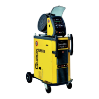
| Model | Qubox 405W PULSE |
| Category | Portable Generator |
| Language | English |