Do you have a question about the Cebora POWER SPOT 5500 and is the answer not in the manual?
Purpose of the manual to train personnel for maintenance on the power source art. 2153.
Customer responsibility for equipment use, maintenance, and qualified personnel for repairs.
Safety notes are integral; disconnect power, wait for capacitor discharge, measure voltage.
Instructions for electromagnetic compatibility to be followed as per Instruction Manual.
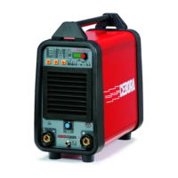
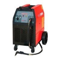
POWER SPOT 5500 system for welding ferrous/non-ferrous studs/rivets, made of electronic power source and accessories.
Refer to machine plate, Instruction Manual, and Sales Catalogue for technical specifications.
Capacitor discharge power source with transformer, rectifier, capacitors, and static switch.
Remove dust from vents, check output terminals/cables, and internal connections/connectors for damage or looseness.
Represents correct machine functioning and can be used for troubleshooting after repairs.
Diagram showing front panel controls and connections for the power source.
Step-by-step procedure for powering on the system, connecting accessories, and initial checks.
Troubleshooting steps for no power and unlit control panel LED, including mains suitability and connection tests.
Troubleshooting steps for a stopped fan, including fan test, wiring checks, and power board replacement.
Troubleshooting steps for the start button not working, including command test, wiring, and component checks.
Troubleshooting for irregular open circuit voltage on DC-capacitors, involving voltage adjustment test and component checks.
Troubleshooting for irregular output voltage during resistive load test, including load test, wiring, and component checks.
Troubleshooting for poor welding quality under high currents, checking accessories, sheet metal, and DC-capacitors efficiency.
Error E1: Transformer overtemperature. System blocks, fan runs. Reset automatically when cooled.
Error E2: SCR short-circuited. No voltage on output terminals, hazardous for positioning.
Error E3: Irregular DC voltage on capacitors. Triac defect or short-circuit. Blocks power circuit.
Error E4: Irregular or slow capacitor charging. Voltage regulator inefficient. Blocks welding.
Error E5: Irregular capacitor discharge. Discharge resistor faulty or interrupted. Blocks system.
Reference to a separate PDF file for the power source component list.
Reference to a separate PDF file for the components table.
Lists essential and recommended spare parts for the power source unit.
Reference to a separate PDF file containing the electrical diagrams for the power source.
Displays waveforms related to the power source operation, specifically output voltage.
Illustrates the output voltage waveform when the SCR engages, as described in troubleshooting section.
Diagram showing the physical layout and component placement on the power board.
Details connectors on the power board, their terminals, and functions.
Diagram showing the physical layout and component placement on the control board.
Details connectors on the control board, their terminals, and functions.
| Brand | Cebora |
|---|---|
| Model | POWER SPOT 5500 |
| Category | Portable Generator |
| Language | English |