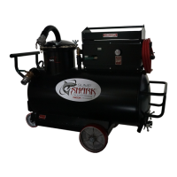
The CEECOR SA5 Horizontal Tank Series, also known as the Sump Shark, is a robust and versatile sump cleaning equipment designed for industrial applications. It is engineered to efficiently remove and filter various fluids and solids from machine sumps, making it an essential tool for maintaining clean and operational machinery in manufacturing and other industrial settings. The SA5 series is available in 90-600 gallon capacities, offering flexibility to suit different operational scales.
Function Description:
The primary function of the SA5 Sump Shark is to clean machine sumps by vacuuming out contaminated fluids, filtering out solids, and then returning the cleaned fluid or discharging it as waste. It operates in both suction and discharge modes, allowing for comprehensive sump maintenance. The unit is designed to handle standard metalworking fluids (water-base & cutting oils) but is explicitly cautioned against use with flammable, corrosive, toxic, or reactive materials. It is also not suitable for use in extra-high temperature or spark-hazard environments (e.g., ovens, welding areas).
The SA5 utilizes a vacuum/pressure selector valve to switch between suction and discharge operations. In suction mode, it draws fluid and solids from the sump into the tank. The fluid then passes through a filtration system, which can include various filter bags (poly, coarse, fine) and a filter basket assembly (F10 or F23 filter, depending on the model). The filtered fluid is collected in the tank, and solids are retained in the filter bags or basket. In discharge mode, the cleaned fluid can be returned to the machine sump or transferred to another container.
Important Technical Specifications:
- Models: SA5 Horizontal Tank Series
- Capacities: 90-600 Gallons
- Operating Discharge Pressure: 6 PSI
- Tank Discharge Pressure (Max): 10 PSI
- Air Supply Requirement: Minimum 3/8" disconnect (1/4" blow-off connections are too limiting)
- Filter Types: F10 Filter (basket assembly), F23 Filter (sleeve type), Poly Strainer Bag, Coarse Strainer Bag, Fine Strainer Bag.
- Wheels & Casters:
- "PTL" Push Tow Lift Wheel Transport (90-200 GAL): Swivel Caster with Poly Tired Wheel (SP-365), Wheel Poly Tired (SP-553).
- "TW" Tow Wheel Transport (300 & 400 GAL): Swivel Caster with Rubber Tire (SP-270), Wheel with Rubber Tire (SP-271).
- "TW" Tow Wheel Transport (500 GAL): Swivel Caster with Rubber Tire (SP-270), Wheel with Rubber Tire (SP-275).
- Tank Assembly (Need to specify gallon capacity and transport): A220-750
- H-Tank Pump Assembly SA5 Air: A220-768
- Tool Box (90-200 only): A220-760
- Filter, Tools & Hose Components:
- Poly Strainer Bag 1 cu.ft.: B210-530
- Coarse Strainer Bag 1 cu.ft.: A210-529C
- Fine Strainer Bag 1 cu.ft.: A210-529F
- Flare Nozzle: A220-149
- Straight Nozzle: A210-474
- Flex Nozzle: A220-150
- Sump Cleaner Hose 16' Orange: A220-142
- Coupler Assembly: A220-864
- Coupler Gasket: SP-262BN-2
- Air Hose ½" x 20': SP-173
- F10 Basket Assembly: A210-431
- Tank Connections, Gauge, Pump Consumables:
- Pressure Safe Cap: SP-611
- Pressure Safe Quick Disconnect Adapter Male: SP-612
- Pressure Relief: SP-437K
- Vacuum/Pressure Gauge: SP-195
- Valve, Butterfly: SP-483
- Butterfly Selector Valve: SP-464
- Butterfly Valve: SP-465
- Pot Lid Gasket: A210-305
- Security Chain: SP-373
- Wing Nut: SP-104
- Hose: SP-5721
- Rupture Disc: SP-382
- Muffler: SP-559
- Quick Disconnect Adapter Male Threads: SP-375
- Cleanout Door Gasket (300-600 only): A210-165
- Cleanout Door Assembly (300-600 only): A220-240
- F23 Filter Components:
- Wing Nut: SP-104
- Filter Lid Gasket: A220-102
- Filter Lid Assembly: A220-103
- Disconnect Adapter: SP-612
- Security Chain: SP-373
- Pressure Safe Cap: SP-611
- Coupler Gasket: SP-262BN-2
- F23 Filter Sleeve Coarse (Not Shown): A220-645
- F23 Filter Sleeve Green Poly (Not Shown): A220-101
- F23 Filter Sleeve Fine Cotton (Not Shown): A220-731
Usage Features:
- Unit Identification: The model and serial number are located on a nameplate on the back panel of the pump base. This information is crucial for ordering parts and for warranty claims.
- Sump Cleaner Features: The unit includes a suction port, discharge port, vacuum/pressure selector valve, vacuum/pressure gauge, air supply valve, and a removable toolbox.
- Installation: For shipping purposes, some models may require the installation of the discharge valve and quick disconnect adapter. Pipe sealant should be used on all joints and tightened securely. Loose items such as filter baskets, filter assemblies, nozzles, hoses, and the toolbox should be reviewed against the packing list upon receipt.
- Initial Startup:
- Close and secure all tank suction and discharge ports.
- Connect to an air supply system that fits the air system. The Shark's air-line terminates in ½" NPT pipe thread. A minimum 3/8" disconnect is required; 1/4" blow-off connections are too limiting for optimal performance.
- Run the unit in "suction" mode. With the air supply valve in the off position, connect the air-line to the system. Turn the selector valve to suction.
- Open the air supply valve. The vacuum reading should increase to 20-26" HG.
- Close the air supply valve.
- Run the unit in "discharge" mode. Change the pump-to-tank hose to the discharge connection.
- Open the air supply valve. The pressure reading should increase to 5-7 PSI.
- Close the air supply valve. Turn the selector valve to suction. The positive pressure in the tank will be released through the vacuum system. If pressure needs to be relieved faster, run the unit on suction mode until the gauge reads "0".
- The machine is ready to use.
- Cleaning a Sump:
- Attach the sump cleaner hose to the suction port and insert the suction tool into the hose end.
- Run the unit in suction mode (refer to initial startup 3.5, step 3).
- When vacuuming out the sump, attack the solids first. Position the suction tool in the areas that are primarily solids. Occasionally, move the suction tool from the solid particulate into a primarily fluidic area. This action will clear the hose of solids, reducing the chances of possibly plugging the hose.
- When the tank is full, the float control (located inside the sump cleaner) will cut off suction to the pump, isolating the pump from the tank (pump will keep running). When this happens, the vacuum reading will fall to zero, indicating the tank needs to be emptied.
- When the filter is full or blinded, the vacuum/pressure gauge will read 10" HG, but there will be no suction at the nozzle, indicating the filter needs to be emptied.
- Discharging Fluid from the Sump Cleaner:
- Attach the sump cleaner hose to the discharge port and cap the suction port.
- Run the unit in discharge mode (refer to initial startup 3.5, step 6).
- Point the nozzle at the target where the fluid is to be dispensed. Slowly open the discharge valve. Slugs of air will pass through the hose when the tank approaches empty. These slugs can cause erratic fluid flows and indicate that the discharge valve should be shut off when this occurs.
Maintenance Features:
- Daily Maintenance:
- Check the vacuum/pressure gauge to ensure it is operating and reading correctly. Tank pressure should not exceed 7 PSI.
- Defective relief valves should be replaced immediately.
- Check for gasket leaks and any tank damage.
- Weekly Maintenance:
- Inspect the tank for sludge buildup. Clean the tank if necessary. With some applications, the tank may need to be cleaned more frequently. Always clean the tank between pumping different types of fluids or materials.
- Clean and inspect the tank float control. Ensure that the float ball seals against the gasket. The float control assembly can be assessed through the pot opening in the sump cleaner.
- Clean the filter bag by rinsing it out in lukewarm water.
- Operate the 8 PSI pressure relief handle to ensure it is working.
- Monthly Maintenance:
- Check for wear on pot lid wing nuts and studs.
- Inspect the sump cleaner hose.
- Grease the swivel caster and wheels.
- Semi-Annual Maintenance: Refer to the troubleshooting section for guidance on specific issues.
- Filter Maintenance (F10 Filter):
- Emptying: Discharge liquid from the sump cleaner and let the filter drain for a few minutes before dumping. Loosen the three wing nuts holding the pot lid in place. Remove the filter.
- Installing: Place an empty filter in the metal perforated basket. Tuck handles in between the filter and perforated basket. Ensure cotton banding (poly-filter) or sides of the filter are lying on the pot lid gasket completely without creases. Re-install the pot lid and wing nuts. With the unit in suction mode and the pot lid capped, turn the unit on to tighten the wing nuts. This provides equal pressure on the pot lid gasket, creating the best seal.
- Filter Maintenance (F23 Filter):
- Emptying: Discharge liquid from the sump cleaner and let the filter drain for a few minutes before dumping. Loosen the three wing nuts on the filter assembly. Lift the filter out of the sump cleaner tank using a hoist or forklift. Keep hands and fingers clear of the pot opening when removing the filter. Position the filter above a container into which the sludge is to be emptied. The distance between the bottom of the filter and the container bottom should be approximately 2 to 3 feet to prevent damage to the filter sleeve when dumped. Drain the filters before positioning and using a container with a dry bottom and suitable capacity will help reduce possible filter splash back. Attach a lanyard to the trigger assembly on the filter bottom. Move to a safe distance from the dumping zone (approximately 7 feet). Pull the lanyard to release the latch and the bottom door will open, dumping the filter. After the filter sleeve is empty, roll the bottom of the sleeve up loosely so that the bottom end of the sleeve will be closed and close the bottom door.
- Installing: Loosen the two wing nuts on the filter lid and remove the lid. Place the bottom end of the filter sleeve in the filter. Fold the upper 1 ½" of the filter sleeve, collar out over the lip of the filter so that the gasket in the lid will clamp it in place. Replace the filter lid and tighten the wing nuts securely. Suspend the filter from a hoist or forklift. Open the filter door. Pull the bottom end of the filter sleeve down and fold up loosely so that the bottom end of the sleeve will be closed. Place the filter in the sump cleaner and tighten the wing nuts securely.
- Cleaning the Sump Cleaner:
- Generally, discharging the fluid out of the sump cleaner is all that's needed. Some solids will accumulate in the bottom of the sump and will require a complete cleanout occasionally.
- The SA5 has an easy-to-remove cleanout door that can be accessed by loosening the two wingnuts.
- CAUTION: This equipment is intended for use with standard machine-tool coolant (water-base & cutting oils) only. It should not be used with flammable fluids (i.e., fuels, paint, solvents, etc.), corrosive, toxic or reactive materials. Do not use in extra-high temperature or spark-hazard environments (i.e., ovens, welding areas, etc.). Clean the tank thoroughly on a frequent basis, especially when pumping different types of coolants and solids of different materials. Segregate handling of different coolants.
- Precautions:
- Read the "Operations Manual" completely before attempting to operate the machine.
- Cleanout, pot lid, inlet cap, and hoses must be in place and tightly secured before operation in the discharge mode.
- Tank discharge pressure must not exceed 10 PSI. Regulator and relief valves are set before shipment and should not be changed as the use of excessive pressure could cause serious injury or damage. Operating discharge pressure is 6 PSI.
- Do not attempt to open the pot lid, cleanout, or bleed-off cap before relieving pressure in the tank.
- Block wheels of the machine to prevent unintentional movement.
- Wear safety goggles to protect eyes from splashing liquids.
- Keep hands and fingers clear of the pot opening when removing or replacing the filter basket or filter assembly.
The CEECOR SA5 Sump Shark is designed for durability and ease of maintenance, with readily available replacement parts. For optimal performance and longevity, regular maintenance as outlined in the manual is crucial.