11
INTRODUCTION
Congratulations on your choice of a GLISS gear motor.
All items included in Cedamatic’s wide product range stem
from twenty year of our experience in the sector of automatic
systems, always striving to find new materials and advanced
technologies.
For this reason, nowadays we are able to offer you extremely
reliable products that, thanks to their power, efficiency and
long-lasting features, entirely meet the end user’s require-
ments.
All our products are covered by a guarantee.
Furthermore, an R.C. insurance policy signed with a primary
insurance company, covers any injuries or damages caused
by manufacturing faults.
GENERAL INFORMATION
This automatic system, with 230Vac single-phase power sup-
ply for sliding gates, is available in the following versions:
GLISS 500 MC /OM
for gates with maximum weight equal to 500kg
GLISS 800 MC /8OM
for gates with maximum weight equal to 800kg
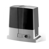
GLISS is a monobloc system featuring a refined design and
reduced dimensions. The motor and an irreversible reduc-
tion system, manufactured with high resistant materials, are
housed in an aluminium container. GLISS is equipped with
spring limit switches. The customised key emergency release
allows to open and close the gate in case of power failure.
Anti-crash safety is ensured by an electronic device (enco-
der and amperometric sensor) which detects any obstacle
present.
PRELIMINARY CHECKS
For a good operation of the automatic system for sliding
gates, the gate or door shall meet the following features:
- the track and relevant wheels must feature correct sizes
and must undergo adequate maintenance (in order to avert
excessive friction during the sliding of the gate).
- during operation, the door shall not excessively oscillate.
- a mechanical stopper (according to regulations in force)
shall limit the opening and closing movements.
INSTALLATION
FIG.1
Overall dimensions of the gear motor expressed in mm.
FITTING OF THE RACK
FIG.3-4
Rack in nylon (Fig.3).
Position the rack at a height of 110 mm from the centre line
of the fixing slot provided on the base on which the founda-
tion plate will be fitted. At that height, drill a hole on the gate
and provide for a M6 threading.
Keep to the P tooth pitch, even from a section of rack and
another. To this purpose, it could be useful to join another
section of rack (Part. C)
Rack in Fe 12x30mm (Fig.4).
Position the spacers D by welding them or fitting them with
screws to the gate, at 143 mm height from the centre line of
the fixing slot provided on the base on which the foundation
plate will be fitted. Fix the rack.
Keep to the P tooth pitch, for all sections of the rack. To
this purpose, it could be useful to connect another section
of rack (Part. C)
Then fix the rack with V screws, taking care, once the actua-
tor is installed, that 1-mm backlash is left between the rack
and the tow wheel (seei Fig.6). To this purpose, use the slots
on the rack.
POSITIONING OF THE FOUNDATION PLATE
FIG. 5-6
It is very important to keep to dimension X shown in Fig.2.
This value depends on the type of rack used:
X = 11 mm for rack in nylon
X = 13 mm for rack in iron, 12x30mm
Preset a corrugated tube (Fig.2 -A) for the passage of power
supply cables and connection wires for the accessories.
Check that, at the end of the fitting, the foundation plate is
perfectly parallel with respect to the wing.
Fitting with screw anchors on cement base)
Through 4 “T” screw anchors in steel (not supplied), firmly
anchor the foundation plate to ground by means of 4 bolts
“B” (not supplied). Use the foundation plate as drilling tem-
plate.
To facilitate the fitting of bolts, 4 holes are provided on the
plate (ref. F).
Fix the geared motor to the plate by means of the 4 screws
V (M10x70), with the relevant plain washers R and knurled
washers, as indicated in the figure.
Installation with cement
In this case, after providing for an adequate foundation hole,
pour cement on the plate, taking care of the plate level. Check
SPECIFICATIONS
GLISS 500 MC GLISS 5O0.O.MC GLISS 800 MC GLISS 8O0.O.MC
Power supply 230Vac 50Hz
Current drawn 1,3 A 2,6 A
Torque 23,5 Nm 34 Nm
Work jogging 30%
Protection level IP44
Operating temperature -20°C / +50°C
Capacitor 12,5 μF 16 μF
Gate max. weight 500kg 800kg
Rack module M4
Opening speed 10,5 m/min
Noise <70 dB
Lubrication CASTROL LP2 AGIP BLASIA 100 CASTROL LP2 AGIP BLASIA 100
Weight 10,6 kg 13,4 kg 11,4 kg 14,2 kg
 Loading...