28 support@cedarsummitplay.com
Step 2: End Wall Prep
Part 2
It is important to assemble the frame on a at, smooth surface.
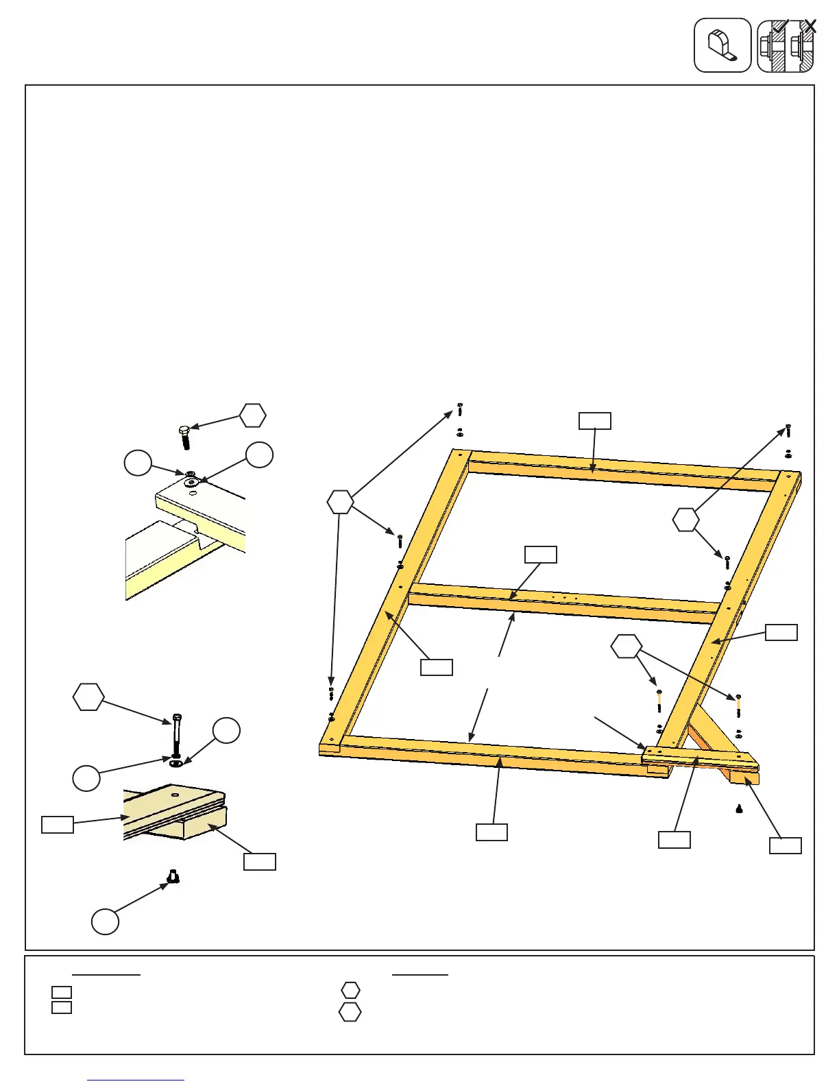
D: Turn the assembly over, make sure distance between (2768) Panel Floor and bottom (2769) measures 42”
then attach all boards with 5 (H9) 1/4 x 1-1/4” Hex Bolts (with lock washer and at washer) connecting to the
previously installed t-nuts. (g. 2.3 and 2.4)
F: Place 1 (2778) SW Ground MOD on the right side of (2769) Panel BT Frame, notice the hole locations and
attach with 1 (H10) 1/4 x 2-1/4” Hex Bolt (with lock washer and at washer) per board connecting to previously
installed t-nuts. (g. 2.3)
G: Place 1 (2607) Diagonal under (2778) SW Ground MOD so the top sits against (2771) End Post and loosely
attach with 1 (H10) 1/4 x 2-1/4” Hex Bolt (with lock washer, at washer and t-nut). (g. 2.3 and 2.5)
H: Repeat steps A-G to make a second End Wall Assembly.
Fig. 2.4
Fig. 2.3
2768
H9
FW1
LW1
2769
Fig. 2.5
10x 1/4x1-1/4”HexBolt(1/4”lockwasher,1/4”atwasher)
4x 1/4x2-1/4”HexBolt(1/4”lockwasher,1/4”atwasherand(2)1/4”t-nut)
2 x SW Ground MOD 5/4 x 4 x 14-1/4”
2 x Diagonal 1-1/4 x 3 x 22”
H9
Wood Parts Hardware
2778
2607
H10
2607
LW1
TN1
FW1
H10
H9
2769
2771
H9
2770
2778
H10
Do not use
this hole
42”
2607
2778


 To Next Page