Do you have a question about the Cedar Summit Paramount F25040 and is the answer not in the manual?
Risk of injury or death from falls to hard surfaces. Install shock-absorbing material.
Maintain a 6-foot obstacle-free safety zone around the play-set.
Adult assembly required; keep small parts away from children.
Owners must maintain the legibility of warning labels on the play equipment.
Prevent use of ropes, loose clothing, and helmets to avoid entanglement.
Ensure equipment is on level ground and properly anchored to prevent tipping.
Rules for safe play including footwear, supervision, and proper use of equipment.
Maintain minimum depth of 9 inches for wood mulch, chips, or rubber mulch.
Requires professional installation and testing to ASTM F1292 safety standard.
Extend surfacing at least 6 feet from equipment; more for swings.
Explanation of wood weathering properties like checking, warping, and fading.
Details on product warranty coverage, exclusions, and residential use limitations.
List of essential tools needed for assembling the play system.
Explanation of how parts are numbered and identified in the manual.
Explanation of common symbols used throughout the assembly instructions.
Guidance on correct installation of lag screws, bolts, washers, and t-nuts.
Tips for organizing wood parts by key number for efficient assembly.
Information on how hardware is packaged and identified for each step.
Instructions on inventorying parts and reading warnings before starting assembly.
Information on how to get help for missing or damaged parts.
Instructions for recording carton IDs and tracking numbers for future reference.
Initial preparation and assembly of front/back walls using panel supports and t-nuts.
Continued assembly of front/back walls using hex bolts, lock washers, and flat washers.
Adding diagonal supports and connecting wall sections with hex bolts and t-nuts.
Initial assembly of end walls using panel supports, panel frames, and wood screws.
Attaching ground mods and diagonal supports to end walls using hex bolts.
Securing diagonal supports to end posts using lag screws and flat washers.
Preparing post assemblies by inserting t-nuts into top and middle holes.
Attaching siding and panel frames to post assemblies using wood screws.
Connecting top panels and floor supports with wafer bolts, lock washers, and flat washers.
Attaching ground mods and diagonals to post assemblies using wafer bolts and hex bolts.
Attaching siding panels to post assemblies using wood and truss screws.
Assembling the large fort frame by connecting narrow panels to end walls using wafer lags.
Connecting front/back walls with and without diagonal supports to the swing wall.
Attaching floor joists to connect wall assemblies using pan screws.
Installing side joists and connecting them to panel floor supports and end walls.
Attaching flat panel brackets and narrow panels to fort walls using pan screws.
Adding diagonal supports to the fort frame using hex bolts and lag screws.
Attaching long floor joists to panel floor supports using wood screws.
Installing floor boards onto the long floor joists and side joists with wood screws.
Assembling the small fort frame by connecting swing walls to front/back walls.
Connecting end walls to front/back walls and swing wall using wafer lags.
Attaching diagonal supports to the small fort frame using hex bolts and lag screws.
Attaching floor joists to panel floors in swing and end walls using wood screws.
Installing side joist mods onto panel floor supports with hex bolts.
Fastening side joist mods to panel floor supports and tightening hex bolts.
Attaching floor boards to floor joists and side joist mods using wood screws.
Positioning large and small forts side-by-side for tunnel connection.
Attaching lower and upper tunnel inserts to forts using truss screws.
Assembling tunnel floor frame by attaching tunnel tops to side joists with t-nuts and screws.
Attaching floor boards and swing brackets to tunnel floor frame with screws and bolts.
Bending and connecting tunnel panels together using connector tabs and nodules.
Joining tunnel sides together at the top using pan bolts and lock nuts.
Sliding the tunnel assembly into position within the large fort and onto the floor.
Securing tunnel assembly to posts, jambs, inserts, and side joists with pan screws.
Attaching upper tunnel inserts to panel supports and tunnel assemblies with screws.
Installing lower jambs in fort openings using truss screws and jamb mounts.
Installing upper jambs in large fort end wall openings using truss screws and mounts.
Installing half wall inserts and mod arches on large fort tunnel side wall.
Installing mod arches and short half walls on large fort front wall.
Installing inserts and side lites on large fort end wall.
Installing mod arches and short half walls on large fort back wall.
Installing window inserts and transoms on small fort front wall.
Installing window inserts, arches, and half walls on small fort tunnel end wall.
Installing short half walls on small fort back wall.
Assembling rock wall panels by attaching access boards and staggered rock boards.
Attaching rock wall assemblies to large fort front wall using wood screws.
Attaching rock wall assemblies to small fort back wall using wood screws.
Securing rock wall assemblies to fort using rebar ground stakes and pan screws.
Attaching rock wall assemblies to large fort front wall using wood screws.
Attaching rock wall assemblies to small fort back wall using wood screws.
Securing rock wall assemblies to fort using rebar ground stakes and pan screws.
Attaching catch plate and door handle to door window panel using screws.
Attaching second door handle and door hinges to door window panel using pan screws.
Assembling counter frame by attaching counter joists to counter back with screws.
Attaching counter assemblies to swing walls using wood screws.
Attaching counter braces to counter joists and swing walls using wood screws.
Attaching counter fronts to counter joists using wood screws.
Attaching counter tops and sides to counter assembly using trim screws.
Installing the faucet and sink knobs into the sink opening.
Securing sink and stove to counter assembly using mount clips.
Assembling slide sections by joining elbows and attaching flange assemblies with pan bolts.
Connecting slide exit tops to slide elbows using pan bolts and clamp rings.
Attaching flange assembly to fort front wall and lower SL insert using pan screws.
Securing flange assembly to panel floor using gussets, pan screws, and wafer lags.
Fitting elbow assemblies to flange assembly and attaching clamp rings with pan bolts.
Connecting and fastening slide clamp rings between elbow assemblies using pan bolts.
Joining elbow assemblies together and attaching clamp rings using pan bolts.
Connecting and fastening slide clamp rings between elbow assemblies using pan bolts.
Assembling large roof supports by joining them at the peak using wood screws.
Connecting roof panels using angle brackets and truss screws.
Attaching large roof support assemblies to roof panels using wood screws.
Assembling small roof supports by joining them at the peak using wood screws.
Connecting small roof panels and attaching supports and grill using screws.
Removing specific hex bolts from fort assemblies, retaining t-nuts.
Loosely attaching roof ends to small fort walls using hex bolts.
Loosely attaching roof ends to large fort end wall using hex bolts and washers.
Measuring overhang and securing roof ends to fort walls using wood screws.
Assembling mid roof supports by joining them at the peak using wood screws.
Placing mid roof support assemblies onto mid roof ends and attaching with wood screws.
Attaching wall ties to floor boards and mid roof supports on large fort walls.
Installing transom windows and flat panel brackets onto fort walls using screws.
Attaching transom windows, flat panel brackets, and corner brackets to fort walls.
Preparing swing wall and attaching steering wheel block with wood screws.
Attaching steering wheel to siding assembly and block using a wafer lag.
| Brand | Cedar Summit |
|---|---|
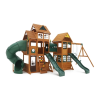
| Model | Paramount F25040 |
| Category | Play Sets & Playground Equipment |
| Language | English |