33 support@cedarsummitplay.com
Step 3: Swing Wall Prep
Part 4
It is important to assemble the frame on a at, smooth surface.
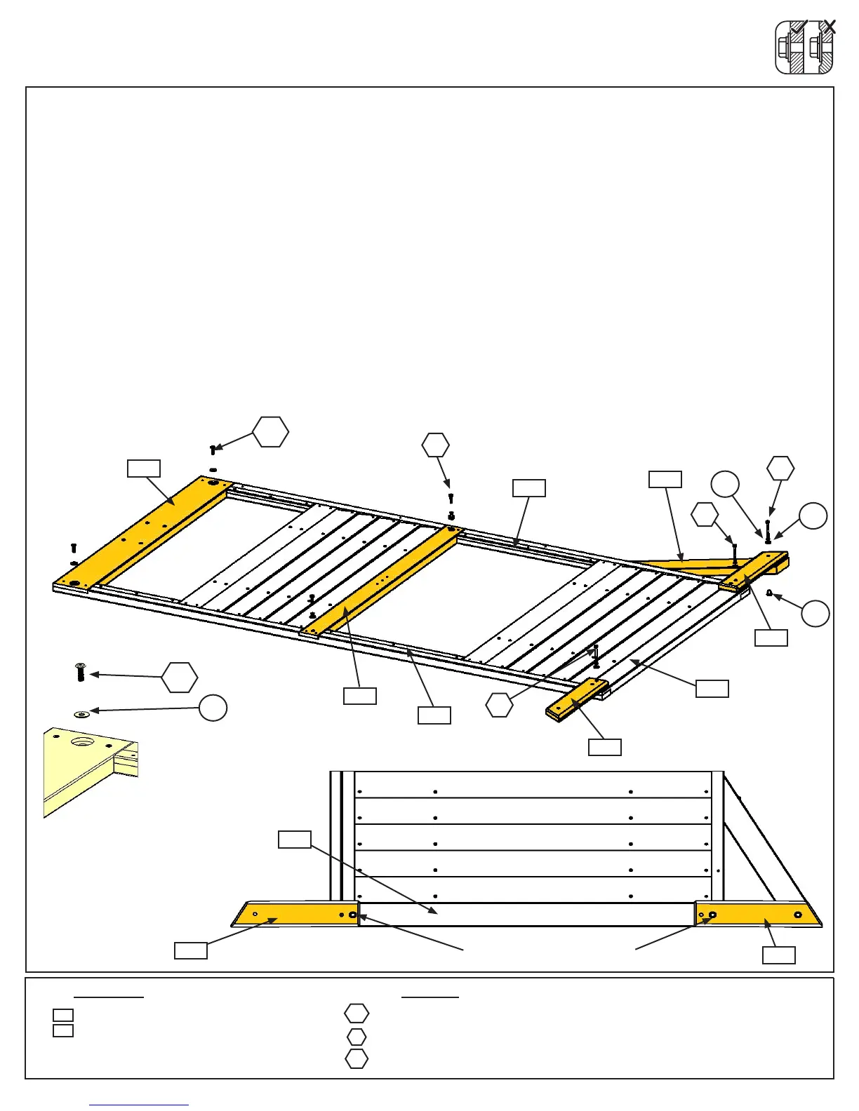
H: On the remaining assembly attach (2630) SW Top to (2757) LT Post Assembly and (2758) RT Post Assembly
with 2 (WB1) 5/16 x 1” Wafer Bolts (with at washer) connecting to previously installed t-nuts per assembly. (g.
3.7 and 3.8)
I: Attach (2768) Panel Floor to (2757) LT Post Assembly and (2758) RT Post Assembly with 2 (H9) 1/4 x 1-1/4”
Hex Bolts (with lock washer and at washer) connecting to previously installed t-nuts per assembly. (g. 3.7)
J: Place 1 (2778) SW Ground MOD to each side of (2769) Panel BT Frame, notice the hole locations and attach
with 1 (H10) 1/4 x 2-1/4” Hex Bolt (with lock washer and at washer) per board connecting to previously installed
t-nuts. (g. 3.7 and 3.9)
K: Place 1 (2607) Diagonal under (2778) SW Ground MOD on the right hand side so the top sits against (2758)
RT Post Assembly and loosely attach with 1 (H10) 1/4 x 2-1/4” Hex Bolt (with lock washer, at washer and t-nut).
(g. 3.7 and 3.9)
2x 5/16x1”WaferBolt(5/16”atwasher)
2x 1/4x1-1/4”HexBolt(1/4”lockwasher,1/4”atwasher)
3x 1/4x2-1/4”HexBolt(1/4”lockwasher,1/4”atwasherand(1)1/4”t-nut)
2 x SW Ground MOD 5/4 x 4 x 14-1/4”
1 x Diagonal 1-1/4 x 3 x 22”
H9
Wood Parts Hardware
2778
Fig. 3.8
Fig. 3.7
2758
2757
Note which bolt holes are used
x 2
2607
2630
2768
WB1
2607
H9
x 3
WB1
WB1
2778
2778
2769
2769
2778
2778
Fig. 3.9
x 2
FW1
LW1
FW2
TN1
H10
H10
H10
H10


 To Next Page