40 support@cedarsummitplay.com
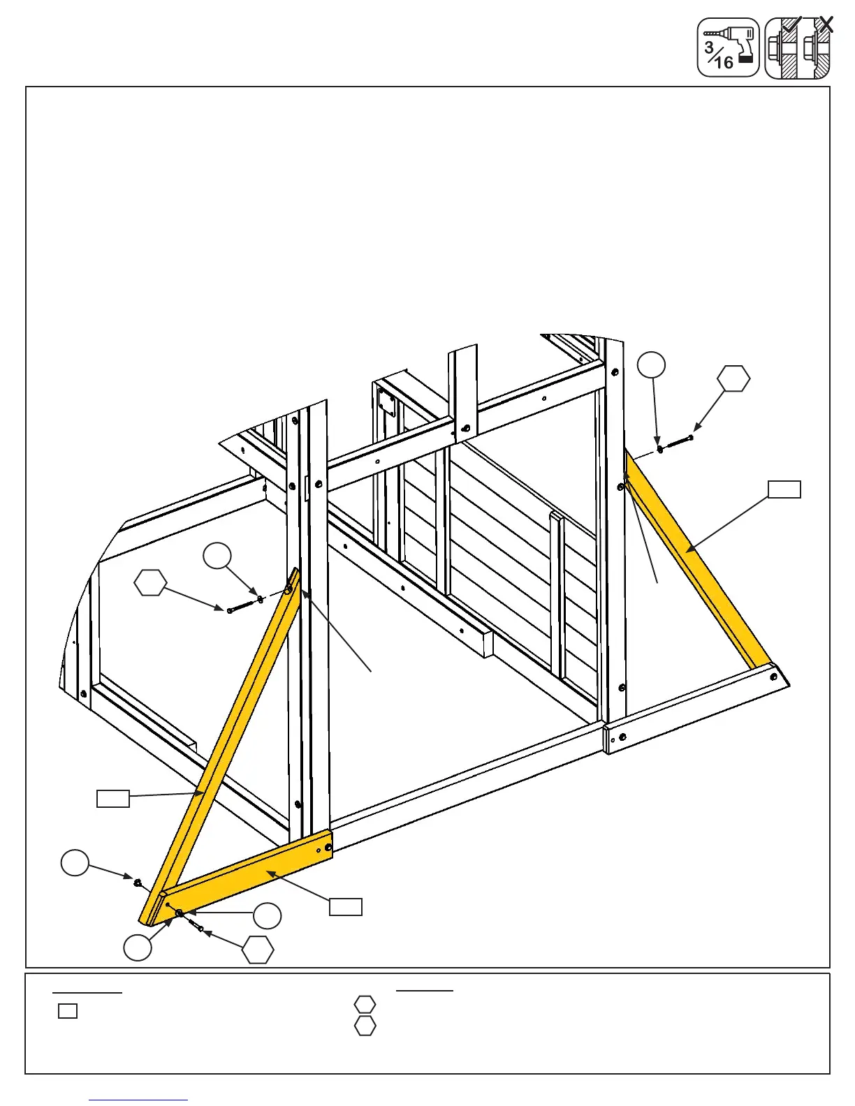
I: On the end Front/Back Wall loosely attach 1 (8587) Diagonal to left (2824) Diagonal Support with 1 (H10) 1/4 x
2-1/4” Hex Bolt (with lock washer, at washer and t-nut). (g. 4.9)
J: Place each (8587) Diagonal tight and ush to the front edge of the Front/Back Wall then pre-drill pilot holes
with a 3/16” drill bit and attach each (8587) Diagonal with 1 (LS3) 1/4 x 3” Lag Screw (with at washer) per board,
checking that they remain ush to front edge. (g. 4.9)
K: Tighten all bolts.
2x 1/4x3”LagScrew(1/4”atwasher)
1x 1/4x2-1/4”HexBolt(1/4”lockwasher,1/4”atwasher,1/4”t-nut)
Hardware
LS3
Fig. 4.9
1 x Diagonal 2 x 3 x 42-1/4”
Wood Parts
8587
H10
Step 4: Large Fort Frame Assembly
Part 6
LW1
Front/Back
Wall
LS3
FW1
Flush
Flush
TN1
FW1
H10
Front
Back
LS3
FW1
2824
8587
8587


 To Next Page