41 support@cedarsummitplay.com
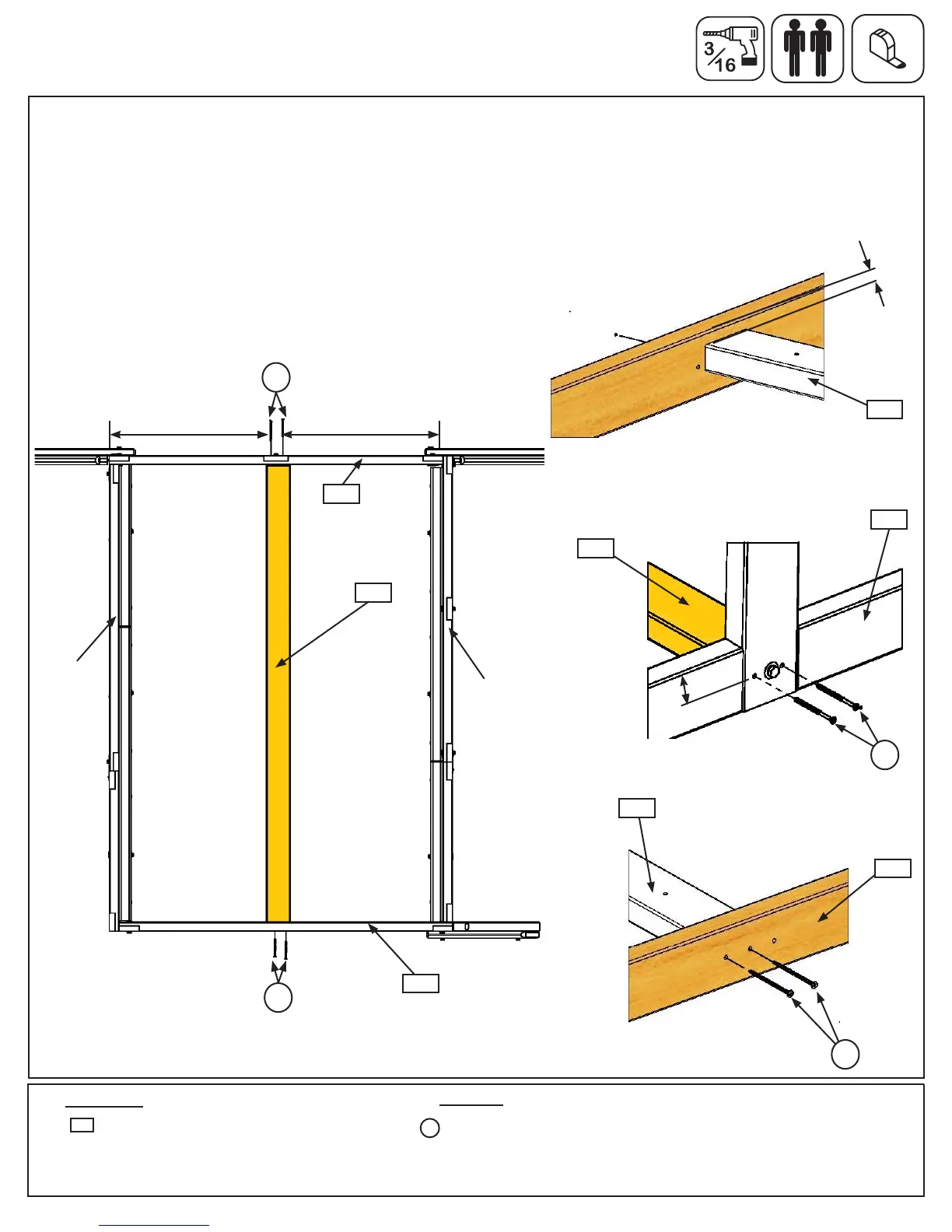
A: On (2772) Panel Floor Support of the Front/Back Wall measure 20-3/8” from the Swing Wall and 21-7/8” from
Front/Back Wall and 1-1/2” down then pre-drill 2 holes with a 3/16” drill bit. (g. 5.1, 5.2, 5.3 and 5.4)
B: From inside of the assembly centre (2681) Long Floor Joist over pilot holes in (2768) Panel Floor on the End
Wall 5/8” down from the top of board and over the pre-drilled holes in (2772) Panel Floor Support on the Front/
Back Wall, then attach (2681) Long Floor Joist to each board with 2 (S4) #8 x 3” Wood Screws per end. (g. 5.1,
5.2, 5.3 and 5.4)
1 x Long Floor Joist 1-1/4 x 3 x 62-5/8”
4 x #8 x 3” Wood Screw
Step 5: Large Fort Floor Assembly
Part 1
2681
Fig. 5.2
Wood Parts
Fig. 5.1
2681
Top View
Fig. 5.3
Hardware
S4
5/8”
S4
S4
2772
End Wall
End Wall
Front/Back Wall
2768
Front/Back Wall
2681
S4
Fig. 5.4
2768
S4
2681
2681
2772
21-7/8”
20-3/8”
Swing
Wall
Front/Back
Wall
1-1/2”


 To Next Page