45 support@cedarsummitplay.com
1x 1/4x2-1/4”HexBolt(1/4”lockwasher,1/4”atwasher,1/4”t-nut)
2x 1/4x3”LagScrew(1/4”atwasher)
Hardware
Wood Parts
1 x Diagonal 1/1/4 x 3 x 22”
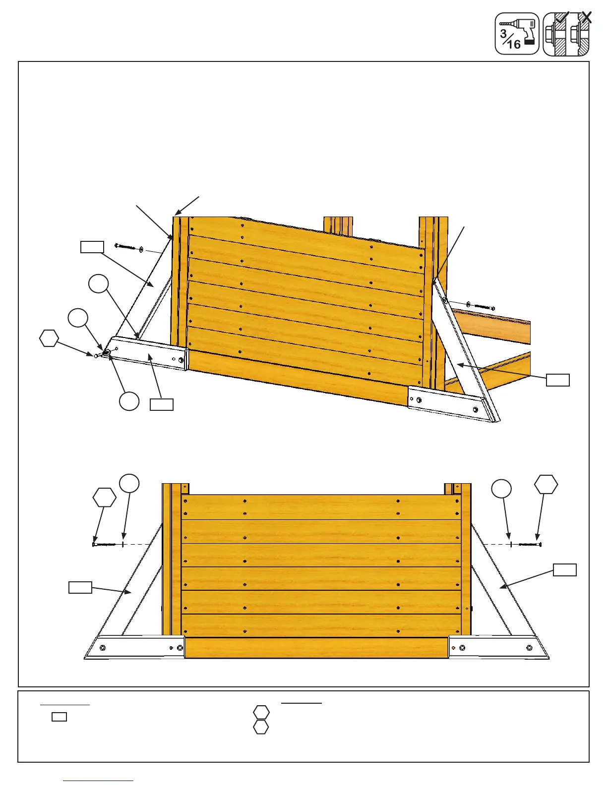
C: Loosely attach 1 (2607) Diagonal to left (2778) SW Ground MOD with 1 (H10) 1/4 x 2-1/4” Hex Bolt (with lock
washer, at washer and t-nut). (g. 6.5)
D: Make sure each (2607) Diagonal is tight and ush to the front edge of the Swing Wall then pre-drill pilot holes
with a 3/16” drill bit and attach each (2607) Diagonal to the Swing Wall and Front/Back Wall with 1 (LS3) 1/4 x 3”
Lag Screw (with at washer) per board, checking that they remain ush to front edge. (g. 6.5 and 6.6)
E: Tighten all bolts.
(hidden)
Flush
LS3
2607
Fig. 6.5
Fig. 6.6
2778
H10
Swing Wall
Flush
LS3
LS3
2607
2607
H10
LW1
FW1
TN1
FW1
FW1
2607
Swing Wall
2607
Step 6: Small Fort Frame Assembly
Part 3
Front/Back Wall


 To Next Page