44 support@cedarsummitplay.com
Hardware
Front/Back Wall
Swing Wall
End Wall
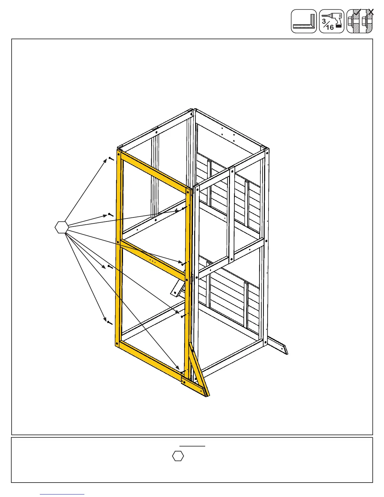
B: Place End Wall from Step 2 between the Front/Back Walls noticing the wall orientation. The tops and
bottoms of the walls should be ush. Make sure the walls are square then using the pilot holes as a guide pre-
drill with a 3/16” drill bit and fasten the right Front/Back Wall to the End Wall and End Wall to the left Front/Back
Wall with 4 (WL5) 1/4 x 2-1/2” Wafer Lags per side. (g. 6.4)
Fig. 6.4
Notice right Front/Back
Wall overlaps End Wall
Notice End Wall
overlaps left Front/
Back Wall
WL5
8 x 1/4 x 2-1/2” Wafer Lag
WL5
Left
Right
Step 6: Small Fort Frame Assembly
Part 2
Front/Back Wall


 To Next Page