97 support@cedarsummitplay.com
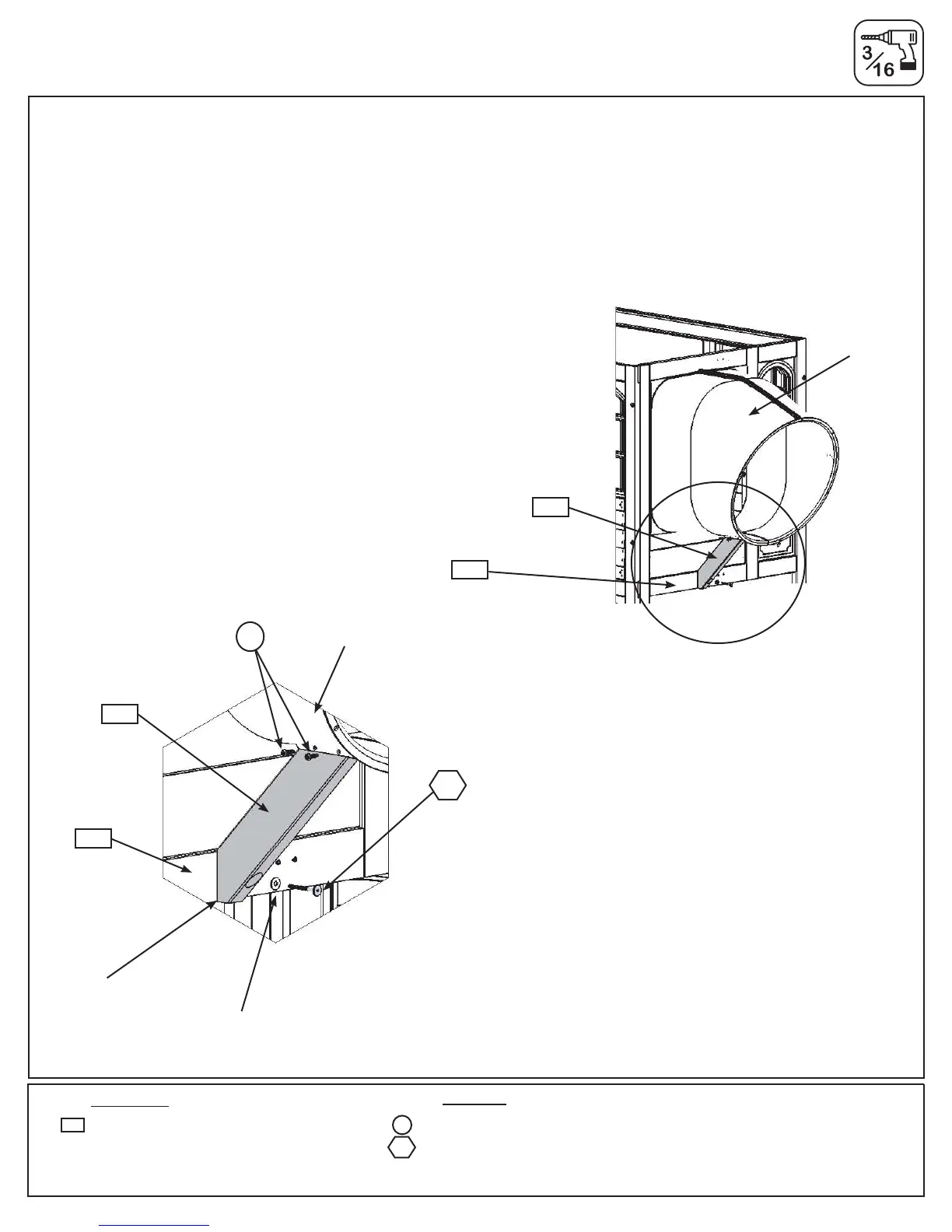
Fig. 32.4
Fig. 32.5
Step 32: Attach Flange Assembly to Fort
Part 2
D: Place (8934) SL Gusset tight to (2768) Panel Floor, ush to the top of the bottom opening and attach to
Flange Assembly with 2 (S6) #12 x 1” Pan Screws. (g. 32.4 and 32.5)
E: Pre-drill pilot hole with a 3/16” drill bit then attach (8934) SL Gusset to (2768) Panel Floor with 1 (WL5) 1/4
x 2-1/2” Wafer Lag (with at washer). (g. 32.4 and 32.5)
2 x #12 x 1” Pan Screw
1x 1/4x2-1/2”WaferLag(1/4”atwasher)
Wood Parts
1 x SL Gusset 1-1/4 x 3 x 15-3/4”
8934
1/4” Flat
Washer
WL5
WL5
S6
Flush
2768
2768
8934
8934
S6
Flange
Assembly
Flange
Assembly
Hardware



 To Next Page