76 support@cedarsummitplay.com
REV.
A
DWG. NO.
SIZE
SCALE:1:50
WEIGHT:
Rock Wall Prep
SHEET 3 OF 3
See details for hardware
7
-
5
/
8
Wood Parts Hardware
Other Parts
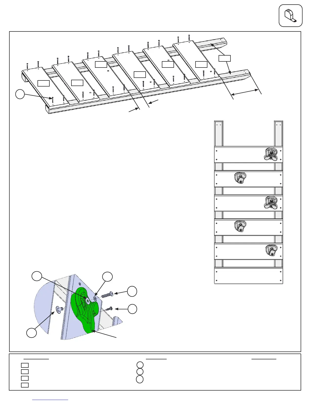
Step 22: Rock Wall Assembly
Complete Step 22, A-E twice to make 2 Rock Wall Assemblies.
A: Lay 2 (2776) Rock Rails down, side by side with angled edges
facing down. (g. 22.1)
B: Place (2779) Access Board on the bottom of each (2776) Rock Rail
as shown in g. 22.1. Make sure (2779) Access Board is ush to the
outside and bottom edges of each (2776). Attach using 4 (S20) #8 x
1-3/8” Wood Screws.
C: 7-5/8” down from the top of both (2776) Rock Rails place 1 (2781)
Rk Board B, making sure the sides are ush to the outside edges of
each (2776) Rock Rail. Attach using 4 (S20) #8 x 1-3/8” Wood Screws.
(g. 22.1)
D: In between the (2779) Access Board and (2781) Rk Board B stagger
2 (2781) Rk Board Bs and 2 (2780) Rk Board As using 4 (S20) #8 x
1-3/8” Wood Screws per board. Placing them as shown in g. 22.1, this
will prevent rocks from forming a straight line. Make sure the boards
are evenly spaced and do not exceed 2-3/8” between boards.
E: Place 1 rock on each (2780) Rk Board A
and (2781) Rk Board B (g. 19.2) and attach
using 1 (PB2) 1/4 x 1-1/4” Pan Bolt (with lock
washer, at washer and barrel nut) and 1
(S10) #8 x 1” Pan Screw per rock. The Screw
must be in the hole directly under the Pan
Bolt, it will stop the rock from spinning. (g.
22.3)
Note: Gaps between boards
2-1/4”, not to exceed 2-3/8”
Note: The holes
in the rock boards
must orient to the
top of the boards.
7-5/8” Approx
Fig. 22.1
2779
2776
2780
2781
2781
27812780
Fig. 22.2
2 x Access Board 1 x 6 x 19”
6 x Rk Board B 1 x 6 x 19”
4 x Rk Board A 1 x 6 x 19”
4 x Rock Rail 1-1/4 x 2-1/2 x 51”
48 x #8 x 1-3/8” Wood Screw
10 x #8 x 1” Pan Screw
10 x 1/4 x 1-1/4” Pan Bolt
(1/4”lockwasher,3/16”atwasher&1/4”barrelnut)
2776
2780
2781
2779
Rock
10 x Rocks (6 green/4 yellow)
S10
S10
PB2
PB2
Fig. 22.3
x 4 per
board
S20
FW0
LW1
BN1
S20


 To Next Page