RIPARAZIONE E SOSTITUZIONE DELLE PARTI
PARTS REPLACEMENT & REPAIRS
9.
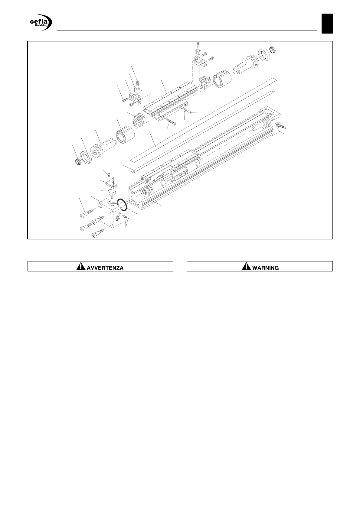
9.6.4 Cilindro senza stelo PNEUMAX
Queste operazioni devono essere eseguite a
MACCHINA FERMA.
- Allentare le viti 20 delle testate 19 e 24;
- Smontare le piastrine 17;
- Liberare le estremità della bandella esterna 14 dalle
piastrine inferiori 18, estraendo le relative spine ela-
stiche con una pinza;
Porre particolare attenzione nel rimuovere i
pattini 8, poiché le molle 9 verranno espulse
durante l’estrazione.
- Svitare le viti 6 e rimuovere i pattini laterali 7 dalla pro-
pria sede;
- Sfilare e rimuovere la bandella esterna 14;
- Rimuovere le piastrine inferiori 18 avendo cura di svi-
tare le relative viti di fissaggio;
- Svitare le viti 20 e rimuovere le testate 19 e 24 dal
corpo del cilindro;
- Sfilare il carrello completo 10 dalla sede del cilindro e
rimuovere la bandella interna 15;
Porre particolare attenzione nel maneggiare la
bandella interna 15, poiché presenta profili
laterali affilati, necessari per ottenere la tenuta
pneumatica, che possono provocare tagli.
- Rimuovere le guarnizioni 1 e 2 tramite un cacciavite,
facendo attenzione a non danneggiare le relative
sedi;
- Svitare le viti di fissaggio 13;
- Rimuovere le coppie composte dai pistoni 3 ed i patti-
ni 4;
9.6.4 Cylinder without rod PNEUMAX
These operations must be performed with the
MACHINE STOPPED.
- unloose the screws 20 from the heads 19 and 24;
- remove the plates 17;
- take away the lower plates 18 from the end sides of
the external strap 14 by extracting the relative lock
spins with a pliers.
Be careful while removing the pads as the
springs will be expelled during the extraction.
- Unscrew the screws 6 and remove the lateral pads 7
out of their housing;
- Extract and remove the external strap 14;
- Remove the lower plates 18 and carefully unscrew
the relative clamp screws;
- Unscrew screws 20 and remove the heads 19 and 24
from the cylinder's body;
- Extract the trolley 10 together with the cylinder
housing and remove the internal strap 15.
Pay attention by handling the internal strap 15:
the operator risks to cut himself as the strap
shows sharp lateral outlines which are
necessary to reach the pneumatic tightness.
- Remove the seals 1 and 2 by the means of a
screwdriver without damaging the correspondent
seats;
- Unscrew the clamp screws 13;
- Remove the units formed by pistons 3 and pads 4;
CEFLA Finishing ed.CE P.49EDIZIONE STANDARD