21
V8.18
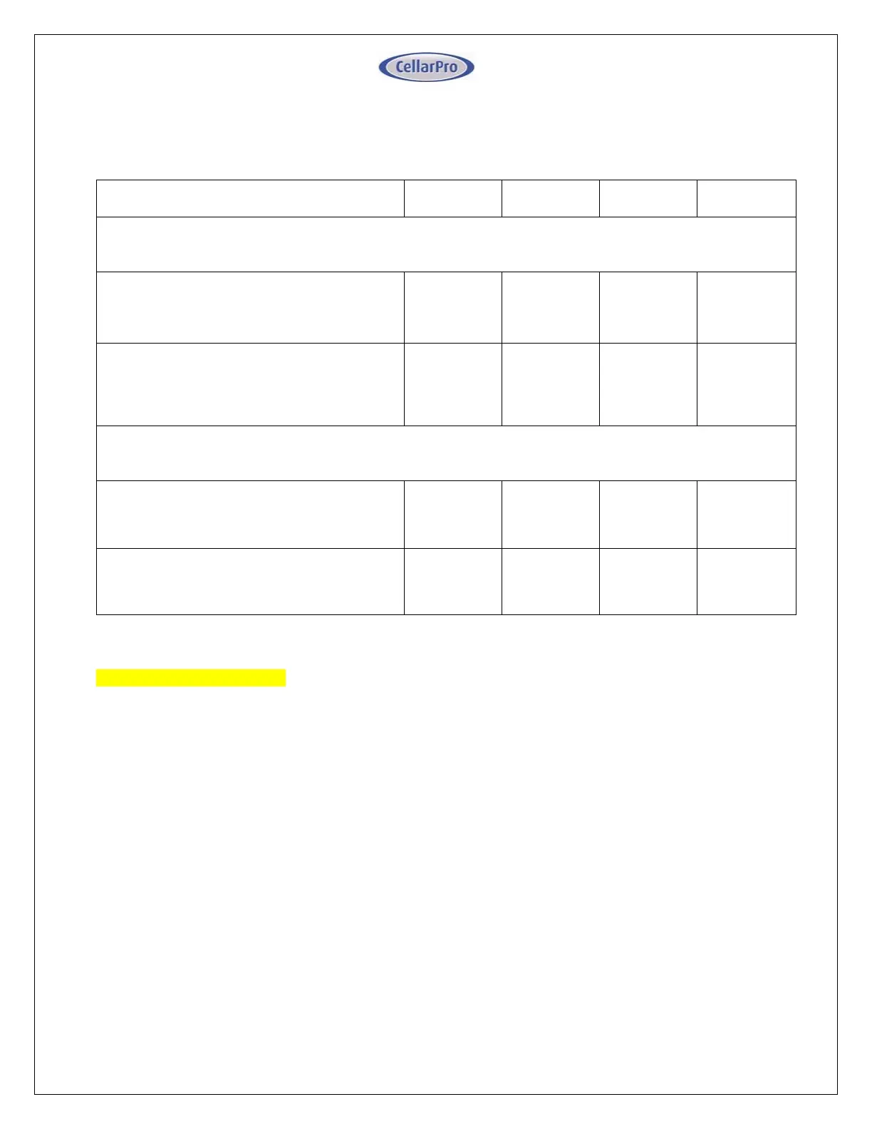
Please refer to the wiring diagram for your configuration in the table below. Note the
difference between 1. Your model, 2. Your choice of wiring configuration and 3. Your
choice of Controller/Thermostat.
System Wiring Configuration
3000S /
3000Sh
4000S /
4000Sh
6000S
8000S
Standard & Remote Controller
Dual Power / Valve Control
Appendix A
1475B_R01
Appendix A
1475B_R01
Appendix B
1475C-R02
Appendix C
1475D_R02
Single Power / Electronic Control
Appendix D
1476B_R01
Appendix D
1476B_R01
Appendix E
1476C_R02
Appendix F
1476D_R02
Networkable Thermostat
Dual Power / Valve Control
Appendix G
2201B_R01
Appendix G
2201B_R01
Appendix H
2201C_R01
Appendix I
2201D_R01
Single Power / Electronic Control
Appendix J
2202B_R01
Appendix J
2202B_R01
Appendix K
2202C_R01
Appendix L
2202D_R01
Important Wiring Notes
If your system is equipped with a compressor heater, make sure it is wired to be
energized even when the system is idle.
If the system has been sitting idle without the compressor heater energized for more
than 24 hours, or if starting up the system in a cold ambient, it is critical to warm the
bottom shell of the compressor above the ambient temperature for 30 minutes
before running the system to drive excess refrigerant out of the compressor oil.
For units configured with a single power source / electronic control, the compressor
heater requires a dedicated line power wire from the evaporator to the compressor
heater. If the power line does not exist, the compressor heater will need to be wired to
an external constant power supply.
 Loading...