58 V8.18
CellarPro Split Systems must be installed by an experienced professional in adherence with industry practices
and as described in the manual. If you need technical assistance during the installation, call 877.726.8496 x2.
Please provide the email address to contact with the warranty activation_______________________________
Technician Name Tech Phone
System Information Piping Information
Customer Name R-134a System Charge(lb)
Condensing Unit Model # Line-set Length (ft)
Condensing Unit Serial #
Liquid line diameter (OD)
Evaporator Model #
Suction line diameter (OD)
Evaporator Serial #
Trap installed in drain line,
charged with water, and
tested for drainage (Y/N)
Power to Condensing Unit (Check One) ____From Evaporator ____From External Source
Power to Compressor Heater (Check One)
- 3000S – 8000S Split Systems
- AH6500 / AH8500S Split Systems
____No Heater ____ Wire “L1” ____Wire “C”
____No Heater ____ Terminal “L1” ____ Terminal “K”
Operational Data: Take the following measurements during a normal refrigeration cycle, once the cellar has pulled down
to the set-point temperature. Make sure the compressor is running when recording the data.
Evaporato
Ran
e
Air temp. at Evap coil (°F) Inlet Outlet TD 8-10°F TD
Evap Fan Speed (Check One) __ High __ Med __ Low
Evaporator power supply Volts Amps
103-127V
nameplate amps
Condensin
Unit
Air temp at Condenser coil (°F) Inlet Outlet TD 20-30°F TD
Condenser fan status __ On __Off
Suction readings at access
valve
PSIG °F SH
25-35 PSIG
20°F Min.
Superheat
Liquid readings at access valve PSIG °F SC
105-180 PSIG
10-20°F
Subcooling
Initial Refrigerant Charge
Through (Check One)
___ Suction Access Valve ___ Liquid Access Valve
Condensing unit power supply Volts Amps
103-127V
nameplate amps
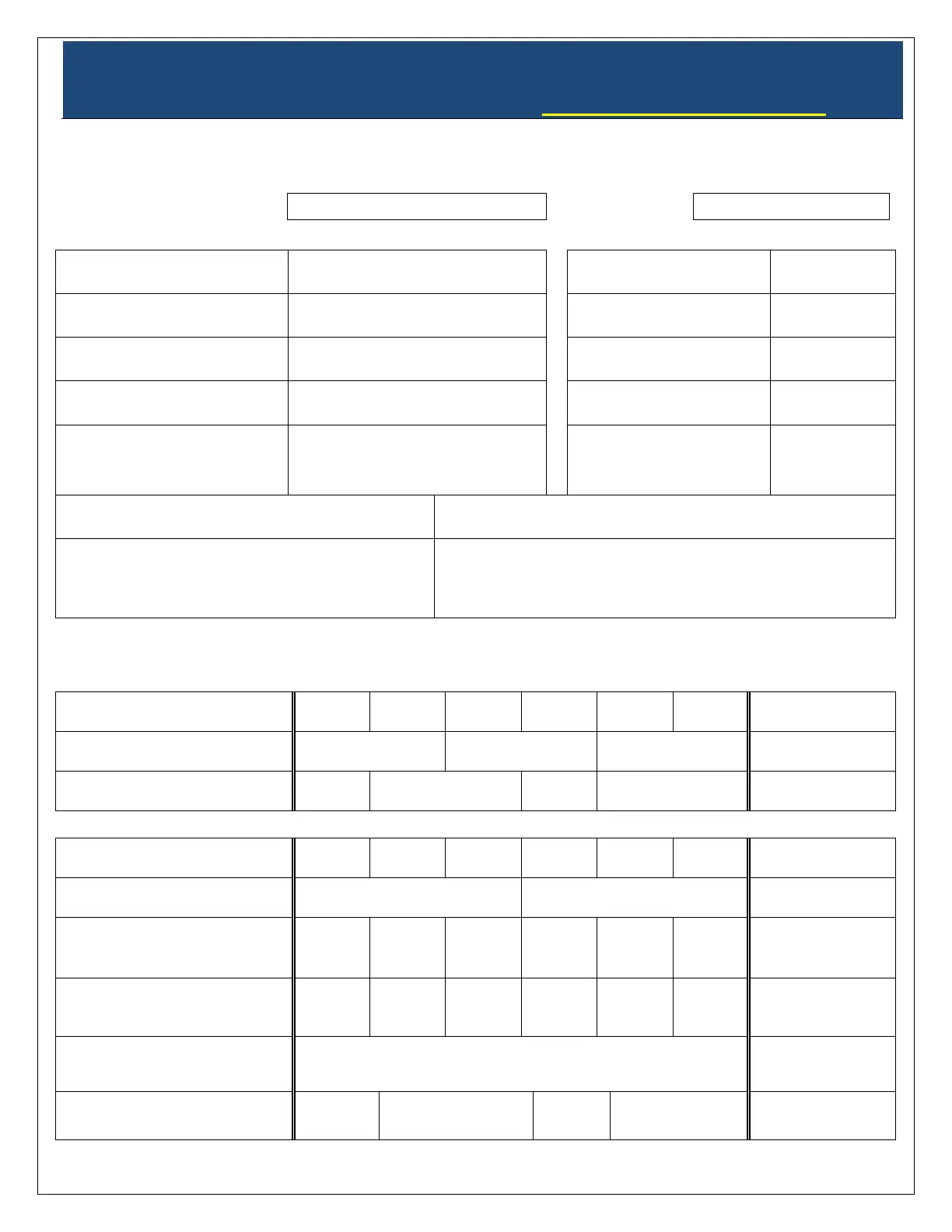
**REQUIRED** TO ACTIVATE THE WARRANTY.
INSTALLERS MUST FILL OUT THIS SHEET AND FAX TO
707.794.8005 OR SCAN & EMAIL TO INFO@CELLARPRO.COM
 Loading...